
User`s manual

About Supervision
of the Wireless Components
About Supervision
Security System 8300 sensors are supervised so
the CCU is alerted if they fail to operate. The
hardwired loops have a supervision resistor at the
circuit board and another mounted at the end of
the hardwire run. The system monitors the
voltage across the local resistor and can sense a
short or open circuit by the change in this voltage.
Depending on the loop type (open or closed), a
short will initiate an alarm or supervision trouble,
and an open will indicate a supervision trouble or
an alarm.
The CCU keeps track of the supervision transmis-
sions of the wireless transmitters (sensor numbers
81 through 112, which send a supervision signal
approximately every 3 hours). If the CCU fails to
receive a message (supervision or change of
state) from any supervised* wireless device
during any one period (the period length is 12
hours) a trouble is generated.
*
Remember that portable transmitters can be designated
as non-supervised (in
Fn#517),
if that device might be
carried out of range.
About Supervision
of the Keypads and CCU
The two most intelligent devices in the system
supervise each other. Within 200 seconds the
CCU will indicate the loss of a keypad (by signal-
ing the remaining keypads with a Trouble report,
“Supv Fail, Central Panel”).
Also within 200 seconds any keypad will signal a
loss of communication link with the CCU, or CCU
breakdown, (by a “Keypad Inactive” message on
the display and Trouble beeps). The beeps can
be quieted by pressing either [SELECT] or [OFF].
of Phone Lines
The system provides two different kinds of phone
line supervision.
First kind: Function
Fn#218
checks the phone line
every hour for operating voltage and reports if 12
consecutive tests are negative.
Second kind (phone block monitoring): The
interior phone line (or lines, if two lines are used)
can be checked for continuity between the CCU
and the premises’ RJ-31 jack. Note that this is
only a supervision of the line as far as the jack,
and not a check of the phone service availability,
(F&218).
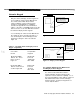
The continuity check is enabled by moving the
jumper in the center of the CCU Main board and
wiring the phone line and jack in accordance with
Figure 2-1 1. Any wire-cut or unplugging will
generate an Interior Tamper (Category 5, hardwire
zone
#10).
Note that this requires an 8-line phone
cord instead of the normally used 4-line.
(
Handling Interruptible
Power for Smoke Sensors
See “Hardwired Smoke Detectors” in Chapter 2
for the explanation of low current applications (75
mA)
using INT AUX power, and a method of
providing a higher current capability for interrupt-
ible power. For UL applications, use only the
direct (75
mA)
method as shown in Figure 2-l 7.
Zones
Refer to Zones in the Glossary.
(‘-
5-6
AT&T Security System 8300 Installer’s Manual