
User`s manual

-
Hardwired Smoke Detectors
Smoke detectors requiring power interruption for
reset after an alarm can be easily enough pow-
ered using the following procedures.
Installation: See the installation instructions
enclosed with the detector for installation consid-
erations.
Basic Wiring: Connect low powered devices
(total of 75mA maximum at 15VDC in the alarm
condition) directly to the INT PWR terminal and
the GND next to it. This method is required for UL
installations. Power from these terminals is turned
OFF for about 5 seconds at each system reset (to
the OFF Level of Protection); the sensor supervi-
sion is interrupted temporarily to facilitate this
without causing a Trouble.
NOTE:
Remember to use the End of Line Relay (power
supervision)-or else the CCU won’t know if the
power lines are tampered.
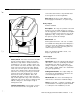
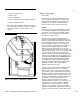
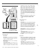
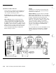
Optional Wiring: A logical method for handling
higher power requirements is to use one of the
CCU’s
built-in relays
(R1
or
R2,
on the left terminal
board) to switch power from the AUX power
(located just above the relay connections). See
Figure 2-l 7. Program the duration selection (Fn#
731 or 741) for these relays to “momentary”
(about 5 seconds) to allow the sensors to reset.
Set the relay to trigger on disarming (Fn#733 or
736, the second character, 0100 0000; and
Fn#732 or 735 to all O’s).
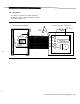
A second method is to use the interruptible 75
mA
supply to power an external relay, controlling
either the AUX power or power from another
source.
Optional
(Non-UL)
.
I
To
anan
fi$
Zone
Interruptable
Power For UL
Applications
Figure 2-17 Hardwired Smoke Detectors
2-24
AT&T Security System 8300 Installer’s Manual