
User`s manual

lected during programming). The CCU provides
drive power for two LED’s that correspond to the
red and green ones on the keypads, and operate
in the same manner.
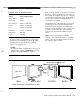
Mount/Install:
Refer to the instruction sheet
supplied with the keyswitch for mounting.
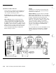
Setting and Connections: See
Figures 2-4 and
2-5 and Figure 2-16. The actual switch wiring is
done to a hardwired zone (1-16) that is pro-
grammed as keyswitch. Additional wiring to the
Ready (green) and Arming (red) LED’s is con-
nected at the left CCU terminal strip, with a
common ground between them.
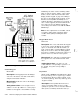
CCU
1
Keyswitch
I
HWZ#
I
1
p$
Hwz
GND
/
Keyswitch#
f
kikister
I
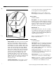
Figure 2-16 Open Loop Keyswitch
NOTE:
For non-UL installations only, you may short
around the two resistors in the keyswitch in order
to make the LED’s brighter.
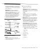
X-10 Power Line Interface
Obtain X-10 devices locally.
Description: An output is provided which will
supply information to the X-10 interface which will,
in turn, switch X-10 control devices as dictated by
programming.
NOTE:
X-10 devices are not to be used as primary
indication devices; use as a secondary device
only. The operation of the X-10 interface has not
been investigated by UL.
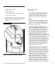
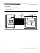
Mount/Install: The X-10 Interface is plugged into
a wall outlet socket. Connection between it and
the CCU is via a normal 4-conductor telephone
cable with standard telephone jacks. Figures 2-4
and 2-5 show the X-l 0 connection on the left
terminal strip near the OFF/ON switch.
Settings/Connection:
Set all X-10 units that are
being used with the security system to the same
house code, one that is different from any others
being used on the same premises. Set the
control devices ID codes to 1 through 8 to match
the 8
triggers listed
here (and in
Fn#741).
1
Intrusion, Interior Tamper, Day Zone, Audible
Panic
2 Silent Panic
3 Fire
4 Emergency
5 Environmental
6 Trouble
7 Auxiliary 1
8 Auxiliary 2
AT&T Security System 8300 Installer’s Manual
2-23