
User`s manual

LCD Viewing
-Angle Adjust
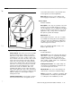
DAT 1
DAT 2
PWR+
COM
AUD 1
AUD 2
* OFF To turn the non-alarm
sounds off; ON allows
non-
alarm sounds to be sounded.
Leave ON for UL installations.
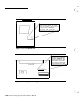
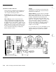
Figure 2-15Keypad Settings and Connections
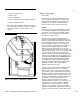
Control Keypad
Model 8340
Description: This keypad provides the ability to
set Level of Protection, enter and sound alarms,
and gives LED status indication.
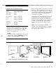
Mount/Install: Mounts the same as the Display
Control keypad.
Settings/Connections:
Refer to Figure 2-15 for
switches. Use the dip switches to set the proper
number for the keypad so that it will be correctly
identified by the CCU. Set the remaining switch
(SW4),
if desired, and the “Chime” control switch
down to cancel sounds listed in the table at the
Display Control Keypad on page 2-21. Wiring is
the same as the Display Control keypad, except
that wires 5 and 6
(AUD1
and AUD2) are not
required (though it is probably best to run them, in
case of future upgrade). Desired maximum wire
run is 300 feet. Like the Display keypad, this
comes with peel-off labels for use with the EMER-
GENCY keys.
Data: Power requirements are 9-l
5VDC;
current
is nominal = 50ma (38ma on battery); Alarm
condition 56ma (44ma) including the alarm
sounder.
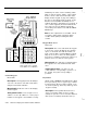
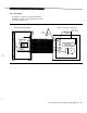
Keypad Desk Cord
Model 8331
Description: This 7-foot cable allows the keypad
to be used as a desk unit without exposing wire
splices, as would be done with the normal
(12-
inch) connector that is provided with the keypad.
May also be used for surface mounting applica-
c
tions where cord will be run along the surface to a
junction. Not for use with UL Listed systems.
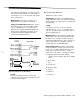
Mount/Install: The cable has a polarized plug for
the keypad at one end, and tinned leads at the
other.
Settings/Connections:
The wires are color
coded, with blue corresponding to position 1 on
the keypad, and yellow corresponding to
position 6.
Keyswitch
Obtain locally, ADEMCO 9789 with tamper switch
#112 (closed loop) or
#113
(open loop); or Alarm
Control Products RP-4 (no tamper switch), Locks
are 2174-70 (flat key), 4073-70 (round key), 5073-
70 (pick resistant).
Description: The keyswitch allows the user to
cause a momentary switch closure to toggle
(switch) the system’s Level of Protection between
OFF (silences an Alarm) and another state
(se-
L
2-22
AT&T Security System 8300 Installer’s Manual