
User`s manual

l COM4 = Audible Panic
l COM5 = Fire
l COM6 = Emergency
l
COM7 =
Environmental,
Aux, Trouble Category
l COM8 = System Trouble
Data:
The output voltage is 6-15 VDC at 25 ma
per channel for 10 minutes or until the condition is
cancelled. (Trouble and Silent Panic do not
cancel.)
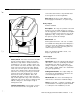
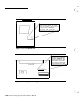
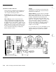
Figure 2-13 Adjunct Communicator Module
2-20
AT&T Security System 8300 Installer’s Manual
Display Control Keypad
Model 8345
Description:
This keypad enables the user to
arm and disarm, and program the system; pro-
vides system information to user via LED’s and
display; and can provide speakerphone and
intercom service (two required for intercom).
NOTES:
Phone and intercom not recommended for noisy
locations. Avoid installing these keypads in the
same room, or facing each other within 20 feet;
feedback can occur between active keypads in
the intercom or phone mode.
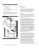
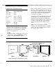
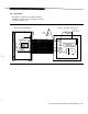
Mount/Install: Figure 2-14 shows how to
surface mount the keypad. Use this device only
where the temperature stays within the limits of 40
to
120°F.
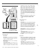
Position the keypad where it is acces-
sible and easily read, but do not put it where it
may be damaged by swinging doors, furniture, or
the movement of children through the traffic
pattern. Avoid placing it where it can be seen
. .
from outside the premises. You can snap the
keypad straight onto or off the mounting plate,
_
and can tilt it upwards almost 90 degrees, for
access to the back. Do not use screws with large
heads on the mounting plate, or the keypad may
not lie flat. Remember that the EMERGENCY keys
are programmable in Security System 8300. If
your system has a special function assigned to
these keys, affix the correct special sticker (from
the set of peel-off labels, provided with the
keypad) between the two keys.
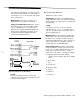
Settings and Connections: Figures 2-4 and
2-5 show keypad wiring at the CCU. Refer to
“Wiring Data,” step 5, page 2-3, for wire informa-
tion. A wired connector is provided to pigtail into
the wire you pulled. Figure 2-15 shows how to set
the switches and connect the wires on the back of
the keypads. Remember to set the I.D. number
so that the CCU can properly identify each
keypad (especially important if the “listen-in”
operation option is chosen). You or the User can
set the volume control to minimum to eliminate
certain sounds and set dip switch
#4
to OFF
(Figure 2-l 5) to eliminate certain sounds (leave
dip switch
#4
ON in UL applications). Table 2-6
shows the sounds and which control affects them.