
User`s manual
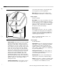
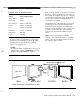
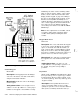
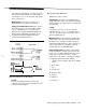
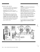
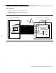

Figure 2-12 Expansion Module
Mount/Install:
This must be done before the Main
board is mounted. Refer to Figure 2-12. Notice
that the base strip and the circuit board have the
mounting holes off center, creating a “wide” side
and a “narrow” side. Place the base strip over the
studs on the lower left side of the CCU, with the
“wide” side out. Then place the small stand-offs
into the space between base strip and stud. This
stand-off is necessary to provide good electrical
ground to the board. Finally place the circuit
board on the studs, also with the “wide” side
(terminal strip) facing out. The edge of the base
strip should support the edge of the circuit board.
Tighten the nuts onto the studs to retain the board
without coming loose, but not tight enough to
damage the board.
Settings/Connections:
Refer to Figures 2-4 and
2-5 for connection of wires to keypads. Do not
connect more than 2 wires to any terminal. Refer
to the keypad text for wire-length limits.
Data: See the previous section, “Battery and
Power Supply Considerations,” for power usage.
Relay Output
Provided standard
Description:
Two relays are provided on the main
board; you can select both the type of response
and the triggering event. If additional interruptible
power is needed for smoke detectors (for non-UL
applications only), a relay can be used with the
Aux power to provide the interrupt.
Mount/Install:
n/a
Settings/Connections: Two sets of contacts
are available from Relay
#1
and from Relay
#2,
a
set that is open in the unalarmed condition and
one that is closed. Relay connecting points are
shown in Figures 2-4 and 2-5.
Data:
The maximum allowable current, 1 .O
Amperes
@
30 volts, DC.
Siren Output
Provided Standard
Description: These two outputs provide power to
drive sirens or horns as specified by the installer
programming. Note that the output may be
steady or cadenced, according to the program-
ming. Length of alarm output is also determined
by system programming.
Settings/Connections:
The output settings are
selected by the programming. Connections are
as shown in Figures 2-4 and 2-5.
Mount/Install: The siren’s current rating at 75
volts must be considered for maximum ratings.
Data: 9-15 volts DC, 1
.O
Ampere each driver, with
a total maximum of 2.0 Amperes (total maximum
is 1
.O
Ampere for UL installations). See the
AT&T Security System 8300 Installer’s Manual
2-
19