
User`s manual


One U.L. listed tamper switch is required in a
commercial burglary installation for protection of
the CCU, and is provided with the commercial
enclosure to protect the enclosure’s door. They
are optional for other installations, and must be
obtained separately for residential installations.
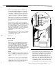
Description: Two switches may be installed to
sense when either the front door of the enclosure
has been opened, or the unit has been pulled off
the wall.
Mount/Install: Figure 2-9 shows installation.
Refer to the figure and mount the back plate and
front cover tamper switches as shown. For closed
loop, wire the switches in series and connect to
the selected hardwired zone. Program to suit the
application requirements (note UL programming
requirements for Tampers, at the end of
Chapter 3).
Settings/Connections: The series loop will be
connected to the zone (1-16) you select in your
programming of the system.
Data:
n/a
Two-Line S
W
i
Model 8321
tcher
Description: If the installation has 2 telephone
lines, the Switcher will alternate between lines
upon call-out failure. Switchable phone block
monitoring is available and goes to hardwired
Zone
#l0,
monitoring continuity between the main
board and the RJ-31X jacks (available from most
electronics supply houses, or from AT&T as
“635B-49, Connecting Block”).
NOTE:
Not for UL installations. This monitors only the “in-
house” continuity, not telephone line outside, and
only the lines between the Switcher and the
RJ-
jacks.
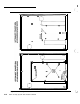
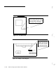
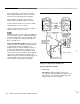
Mount/Install: Figure 2-10 shows installation;
Figures 2-4 and 2-5 show the block monitoring
On/Off jumper (for use if phone lines are vulner-
able between the CCU and the RJ- jacks).
Stand
Off
\
I
crb
0
Out To
Main Board
Line
2
In
Line 1 In
Figure 2-10 Two-Line Switcher
Settings/Connections: Plug the two lines from
the RJ-31X (or RJ-38X) jacks into the switcher
(Note that these are 8-wire, not the common
4-
wire; if you wire this with two 4-wire lines, you
must have one monitor wire in each line, see
Figure 2-11). The connector marked “line 1” will
dial out first. The third line from the switcher goes
to the main board (you can use 8” AT&T 8-wire
cord
D8W-50
for this). Connect the cable from
the switcher board to the main board as shown.
AT&T Security System 8300 Installer’s Manual
2-
17