
User`s manual


Other CCU Devices
CCU POWER TRANSFORMER
Model 8305 (Ault Inc.
Pt#
354-6018-001)
Description: The standard in-line power trans-
former supplies up to 60 volt-amperes of power,
at 18 volts.
Mount/Install: The standard transformer can be
plugged into a normal (polarized) 117 VAC
electrical outlet and mounted horizontally or
vertically. Place or mount the transformer on the
floor (required for UL), where it will not be dam-
aged or wet, and away from the antenna if the
wireless module is used. DO NOT install the
transformer inside (or on top of) the CCU enclo-
sure, since it carries high voltage. UL requires
that the power plug be secured to the outlet plate
with the enclosed plug-tie (Panduit Sta-Strap@
#SSC2S-Sl O-C):
1.
Secure the tie to the center of the outlet
plate with the plate’s screw.
2.
Plug in the transformer.
3.
Loop the tie strap around the cord as
close to the plug as is practical
(1-1/2
or
2”) and pull the tip back through, as with
any cable tie. Pull tight and cut off any
excess.
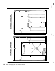
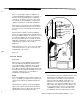
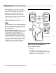
Settings/Connections:
Connect the power cord
(22 gauge, 15 feet maximum) from the transformer
to the transformer as shown in Figures 2-4 and
2-5, before you plug in the transformer.
NOTE:
If a Wireless Module is used, special wiring steps
must be taken; refer to the wireless module.
Data: 117 VAC input, 18 VAC output at 60 volt-
amperes load.
CCU Power Storage Batteries
Obtain battery (YUASA
NP7-12)
locally.
Description: A single 7 ampere-hour battery is
considered the minimum standard; for non-UL
installations, a second battery can be wired in
parallel for added capacity.
Mount/Install: Position the battery(ies) in the
bottom of the CCU enclosure.
Settings/Connections:
Connect the battery to
the CCU terminal leads (+ to Red, -to Black)
carefully; incorrect polarity can cause rapid
discharge and possible damage.
Data: Rated at 7 ampere-hours.
Dual Battery Harness
Model 8315
Description: Allows you to connect a second
NP7-12
battery in parallel with the first, to double
the standby and alarm time with a battery configu-
ration that will fit into the enclosure (for non-UL
applications). Remember that recharge time may
also double after running the batteries down.
Mount/Install: Unplug the + (red) lead from the
current battery, and plug in the (red) multi-
pronged end of the parallel harness; then replug
the original lead into the same multi-pronged end.
Plug the other end of the (red) harness into the +
(red) terminal of the second battery. Repeat the
operation with the
-
(black) connectors.
AT&T Security System 8300 Installer’s Manual
2-15