
User`s manual


2.
Have the antenna knockout (if unused)
plugged with appropriate sized conduit
blanks (Hoffman hole seals:
A-S100
for 1”
holes, A-SO75 for
3/4”
antenna hole).
3.
Be secured with six 2” 8-32 screws,
provided (four through the side, one each
through the top and bottom, in the
threaded holes provided) in the panel door
to slow any attacker.
4.
Use conduit for exposed wiring.
Mount/Install: Mount the enclosure first, without
the main board or options. Then mount the Main
Board in the enclosure:
NOTE:
We advise that you wait until all wires are run and
connected to the terminal strips before you mount
the CCU Main Board.
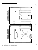
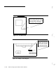
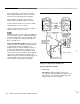
1.
Place the
7/8”
long spacers on the studs
as shown in Figure 2-7. If neither of the
expansion strips is used, you will install all
8 spacers; if you use the keypad expan-
sion strip don’t use the lower left spacer, if
you use the ADCOM (adjunct communica-
tor) don’t use the lower right spacer.
2.
The Main Board is not likely to be dam-
aged by static electricity during handling,
but this step will help reduce any possibil-
ity of damage. To pick the board up, first
touch the table that it is on; then use the
other hand to hold one side of the board;
finally, pick the board up with both hands
to avoid mechanical damage.
3.
When mounting the board in the enclo-
sure, first touch an elbow or wrist to the
enclosure to “trickle off” any voltage
difference.
NOTE:
The board is quite large. Because ofits
size, it may be damaged by flexing or
bending. Align the main board over the
pins and the studs. Do not flex it unneces-
sarily while pressing it onto the pins;
instead, position it carefully and press
firmly and evenly on the area of the board
4
A
A
directly above the pins.
Be
careful since
the pins may extend slightly through the
connectors; you could stick yourself on the
tips of these pins. Since the board is
large, slide it onto the pins in “sections.”
First ease the top of the board
1/4”
onto
the pins, then the middle, then the bottom.
Continue to carefully work the board all of
the way onto the pins without putting
unnecessary stress on it.
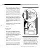
Install seven 8-32 nuts at the edges of the
board and on the heat sink, and the plastic
nut on the lower right corner of the board.
Install six 6-32 nuts in the central area of
the board as shown in Figure 2-7.
WARNING:
Use
the plastic nut as noted, to protect
against electrical damage.
WARNING:
It is critical that the board’s heat sink be
properly bolted to the enclosure, or the
electronics may be destroyed.
Settings/Connections:
The main board does not
require special switch settings. The OFF/ON
switch is shown in Figures 2-4 and 2-5. Refer to
Figures 2-4 and 2-5 for connection information.
Data: Current ratings, see “Battery and Power
Supply Considerations” on page 2-9. Ringer
Equivalence for phone connections, 1.4.
AT&T Security System 8300 installer’s Manual
2-13