
User`s manual

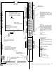
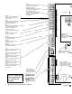

R1
COM
Relay 1 terminal connecting to the
common for the relays Open and
Closed contacts.
R1 NC
Relay 1 terminal to the contacts that
are closed except when the relay is
energized.
1
ampere rating.
R1
NO
Relay 1 terminal to the contacts that
are closed except when the relay is
energized.
1
ampere rating.
R2 COM, R2 NC, R2 NO
The same connections as for Relay 1.
RDY LED
Connect to the positive side of the
keyswitch’s green LED
RDY GND
Connect to the negative/ground side of
the keyswitch’s RDY LED
ARM LED
Connect to the positive side of the
keyswitch’s red LED
ARM GND
Connect to the neative/ground side of
-
the keyswitch’s AR
1
M LED
DAT
1
Connect no more than 2 (22ga) wires
from keypad connector pm
#1
DAT 2
Connect no more than 2 (22ga) wires
from
keypad connector pm
#2
PWR+
Connect no more than 2 (22ga) wires
from keypad connector pm
#3
COM
Connect no more than 2 (22ga) wires
from keypad connector pm
#4
AUD 1
Connect no more than 2 (22ga) wires
from keypad connector pm
#5
AUD 2
Connect no more than 2 (22ga) wires
from keypad connector pin
#6
See UL Note 4
LOW AC
Connect these power inputs from the
transformer to these 2 terminal.
AUX
PWR+,
AUX
PWR-
Connect devices requiring 1 O-1 5 VDC,
(400ma total current) power here.
SIR1-,
SIREN1&2+,
SIR2-
Connect the (-) siren 1 lead to
SIR1-
and the (t) to either SlREN1&2+. Do
the same way for siren 2.
See
UL
Note 2
Do
use Green Wire
(earth) ground for
UL Commercial
Burglary.
q
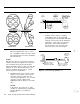
ON/OFF
SWITCH
X-10 CONNECTOR
Plug in the 4-conductor
phone-type cable from the
X-10 Controller module
Connect extra
keypads
to this module, in the
d
same order as
specified
above
-I
1
1
1
1
1
iil
See UL Note 1
’
ON
OFFOFF
WIRELESS MODULE
CONNECTOR
Plug in the cable from
tl
module here. Housecode is
the module itself.
/
p‘
J
Z-LINE SWITCHER
CONNECTDI
Connect the cable from the
switchc
module here.
PHONE CONNECTOR
Connect the phone cable frc
RJ-31X phone jack, or else th
cable from the
2-line
switcher.
Equivalences are 0.4A and
0.7E
GROUNDHERE
GROUN
Used fo
initiate
(
2-8
AT&T Security System 8300 Installer’s Manual
Figure
2-5
1
S