
User`s manual


\
\
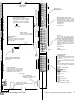
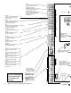
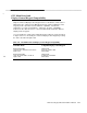
MAIN BOARD
(Not to scale)
1
3
1
1
1
1
LITHIUM BATTERY JUMPER
Move jumper to ON (left) to enable
battery support of systems memory. If
not enabled, shut down or removal of
power will cause loss of program.
0
ON
OFF
RESET BUTTON
Press to reset all system
memory to its factory default.
WIRELESS MODULE
CONNECTOR
Plug in the cable from the wireless
module here. Housecode is selected on
the module itself.
\ \
-I
k
ON
OFF
2-LINE SWITCHER CONNECTOR
Connect the cable from the switcher
module here.
PHONE CONNECTOR
Connect the phone cable from the
RJ-31X
phone jack, or else the short
cable from the
2-line
switcher. Ringer
Equivalences are
0.4A
and 0.78.
See UL Note 1
LOCAL CONNECTOR
Connect RS-232 cable for direct
CCUBOSS programming.
dl
GROUND START RELAY
Used for only if grounding is required to
initiate dial tone.
9
PHONE BLOCK
/
MONITOR JUMPER
J
HARDWIRE
ZONE CONNECTORS
Each numbered zone has a terminal with
that number. Next to each is a GND
terminal for the return wire. Up to two
22 gauge wires may be connected to any
ground terminal.
See UL Note 2
See UL Note 6
INT PWR
This is a low-current source (75 ma
max) of 9-15 VDC interuptable power
(typically used for glassbreak detectors
or relays controlling other power). Do
not use devices which could draw more
than 75mA in the alarm condition
.
Power is interrupted for 5
d
secon
s
whenever system is set to OFF Level of
Protection.
See UL Note
5
BLANK
Not currently used.
OPTIONAL ADJUNCT
COMMUNICATOR
These terminals provide
6-15VDC,
at up
to 25ma to indicate each of the
8-channel
messaaes to
the
communicator (see‘ Programming,
Fn#235).
GND
This is the ground terminal for the return
wire from the Adjunct Communicator.
COM8
Indicates ‘System Trouble’
COM7
Indicates
‘Auxiliary’
Indicates ‘Emergency’
COM5
Indicates ‘Fire’
COM4
Indicates ‘Panic’
COM3
Indicates ‘Silent Panic’
COM2
Indicates ‘Intrusion, Interior’
COM1
Indicates ‘Intrusion, Perimeter’
023),
and Medical
(UL#1637)--See
Notes
AT&T Security System 8300 Installer’s Manual
2-7