
User`s manual


--
17.
18.
19.
20.
Verify that system operates properly in
each Level of Protection (OFF, DAY,
NIGHT, and AWAY) by setting the system
to that Level and actually verifying re-
sponses.
a.
b
C.
d.
LED operation at every keypad, under
every condition.
Presence of keybeeps, chimes, tones,
and alarm sound at Display Control
Keypads.
Operation of every entry key (as
signified by a keybeep).
Operation of Emergency and Police
key pairs.
Verify that the system communicates
properly with the Monitoring Service, using
the test procedures accepted by the
Service (connect the phone line to the
system first).
Verify or program correct house code into
the X-l 0 devices and control circuit, and
connect the X-10 wall cube and slave
device(s). Verify that the controlled
devices operate correctly by energizing
them from Fn# 013.
Connect the other peripheral devices
(sounders and relay-controlled devices;
UL and NFPA require that sounders be
located indoors). Test these devices
using Fn# 011 and 012.
21.
Do a full system test.
22.
Use your company’s checklist to make
your presentation of the system to the
owner/ user. Remember that a well-
prepared user will result in more satisfac-
tion, fewer callbacks, and positive word-of-
mouth advertising in a business that profits
greatly from customer recommendations.
Wiring Data
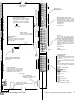
1.
Use Earth Ground for the CCU except in
UL listed Residential Fire applications.
The preferred ground is an 8 foot copper
clad ground rod located close to the
power and telephone ground rods, and
electrically connected to each. Conduc-
tive metal cold water pipe may constitute a
valid earth ground. Connect (solid 14
gauge) wire from the earth to any one of
the 4 corner mounting screws of the CCU
main board. Keep the wire as short as is
practical, don’t coil or bend it, and don’t
run it with other wires.
2.
Use a minimum of 22 gauge wire for
system wiring and do all wiring in accor-
dance with national and local codes.
3.
If your installation uses the wireless
module and transmitters, reception will be
greatly improved by keeping the wiring
down and away from the module and
antenna. Run wires into the enclosure at
the bottom.
4.
You may connect no more than 2 wires to
any CCU terminal strip connector. If you
have 3 wires, you must find another
connector for the third wire.
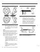
5.
Keypads (Display and Control) require
three twisted pair, 22 gauge-such as
Belden solid 8742 (non-UL), stranded
9745 (non-UL), or 2464 (UL), or equiva-
lent.
A possible (non-UL) alternative is
22-
gauge, 4-conductor, phone wire plus a
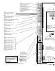
twisted pair of 22-gauge. Refer to Figure
2-l. For phone wire, make sure that each
function (Dat or
Aud)
is connected to wire
pairs that are diagonally
opposite each
otner
In
the cable.
AT&T Security System 8300 Installer’s Manual
2-3