
User`s manual

Basic Installation Guidelines
1.
2.
3.
4.
5.
6.
7.
8.
Plan or review the installation.
You may choose to program the CCU at
your workbench before going to the site.
You can do all programming (except for
Fn#519,
mentioned above), or enter only
the information that is considered firm.
This can be accomplished quite easily
with the optional computer program,
CCUBOSS.
Be sure the lithium battery is enabled
(jumpered to the ON position).
Move to installation site.
Check the CCU installation site in terms of:
a.
b.
C.
d.
e.
Having access to the phone line(s)
where they enter the site, or at least in
front of any phone connections.
Having power outlets (preferably within
25 feet) for power supply and X-10
module (if used).
Wireless environment and reception
with the CCU temporarily held in place
(if wireless is used). If necessary,
move sensors or CCU, or use remote
CCU antenna.
Physical mountability of the CCU.
Appearance and accessibility consid-
erations.
Examine the proposed locations for
Display keypads. If they are too close,
acoustically, feedback may occur in
intercom or phone modes.
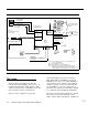
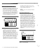
Run and label all wiring. Figure 2-l shows
and labels all connecting points.
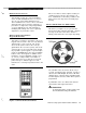
Install the CCU in a safe interior location:
a.
Mount the cabinet and bring the wiring
into it. If your system uses wireless
devices bring all wiring into the enclo-
sure at the bottom, away from the
wireless module and the antenna.
9.
10.
11.
12.
13.
14.
15.
16.
b.
C.
d.
e.
f.
Refer to the Appendix for other wireless
considerations. This will help reception
considerably.
Install the keypad expansion and
adjunct communicator terminal strips, if
needed.
Connect wiring to the terminal strips
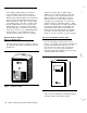
Install CCU options (wireless module
and two-line switcher) if used.
Install main circuit board and plug in
the cables from the options boards.
Do not connect X-10 wall cube, sound-
ers (sirens, horns), or telephone lines
until testing is complete.
Connect power to the CCU.
Configure, hook up, and mount system
sensors (this can be done by a second
installer while the first installer is working
on the CCU).
Hook up and mount the Display Control
Keypads. Verify each one separately as
you connect it.
Hook up Control keypads and mount
them.
If the CCU has not already been pro-
grammed, or if additional or corrective
programming is required, do this now.
Put the system in the Verification Test
mode, Fn# 014 (see Chapter 3 on pro-
gramming).
Perform the Verification Test to verify that
each sensor is operating and properly
identified. Make any necessary changes
or corrections until all existing sensors are
located and properly identified by the
CCU.
Check the CCU programming to see that
only the actual sensors have been acti-
vated in the CCU’s memory. (Use User
Programming to list the Bypassed and the
Unbypassed sensors.) Make the neces-
sary corrections for any incorrect sensor
numbers.
2-2 AT&T Security System 8300 Installer’s Manual