
User`s manual

Note
1
er
1 Display/Control
keypad (8340)
Note 3
1 Control keypad
. . .
. . .
=
(6345) or 8340
6240 Universal
. . .
=
Up to 32 System 8300
Note 2
wireless
Sensors and
Up to 6 additional 6340
_
Communications
l
((
Control
Unit (CCU)
Keypads
and/or 6345
----------
-
I 0
tional
I
|
8301 Software Package
,
and Computer
Keypad.
Expansion Module
I
8320 (Opt.)
I
I
LociI
(on site) Dealer programming
RS-232
p
Interface
I
,-_--,--I
Remote (via telephone)
Dealer programming
6561 Passive
Wireless
Receiver
Keyswitch with
Module
Red
8
Green LED’s
6325 (Opt.)
Auxiliary power output
Up to 16 Hardware
Zones
Interruptable power output
for Smoke Detector reset
Built-in
Relay
1&
2
Dialer
-Note
4-
Siren Drivers 1& 2
Phone line 2
Note 4
Note 1: Turn ON/OFF
&
set levels, User programming, and
Dealer programming.
Note 2: Turn ON/OFF
&
set levels.
Note 3: Turn ON/OFF & set one additional level.
Note 4: Standard output reporting compatible with Slow A,
Slow B, Fast A, Fast B, Sumcheck 2300.
Sumcheck
1400,
DTMF.
SIA(FSK),
and AT&T F.SK reoeiver formats.
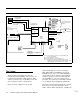
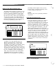
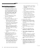
Figure l-l System Diagram
The System
AT&T Security System 8300 offers all of the
normally expected capabilities and more. It is for
residential and small-to-medium business appli-
cations. It can have up to 16 hardwire zones and
up to 32 wireless devices, all supervised.
Figure l-l shows a diagram of the system.
System 8300 supports 4 Levels of Protection
(OFF, DAY, NIGHT, and AWAY) for increased
flexibility in user service. For added flexibility, in
design and set-up, the installer can program the
system’s response to each zone and each wire-
less transmitter for every one of the 4 levels of
protection. The system is provided with a default
set, to minimize the programming requirements.
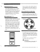
Two types of wired Control keypads can set the 4
basic Levels of Protection; they have status
LED’s, and two-button “Emergency” (definable by
1-2
AT&T Security System 8300 Installer’s Manual