Synapse® Installation Guide © 2010–12 Advanced American Telephones. All Rights Reserved. AT&T and the AT&T logo are trademarks of AT&T Intellectual Property licensed to Advanced American Telephones, San Antonio, TX 78219. Synapse® is a registered trademark of Advanced American Telephones. Issue 17.
Synapse Installation Guide CONTENTS Preface .............................................................................................................. 4 Additional Documentation ................................................................................................................................. 4 Topic Navigation ..................................................................................................................................................... 5 Text Conventions ...........
Synapse Installation Guide Connecting a Fax Machine ............................................................................................................ 46 Connecting an Overhead Paging System (OHP) ................................................................ 47 Connecting a Music on Hold Source ........................................................................................ 49 SB67040 Cordless Handset Installation.........................................................................
Synapse Installation Guide Initial Installation ...............................................................................................................................................105 Display Messages...............................................................................................................................................106 T1 Gateway Indicators ...................................................................................................................
Synapse Installation Guide Back to Contents PREFACE This Installation Guide provides instructions for installing and setting up your Synapse system with software version 2.0 or later. See page 8 for instructions on checking the software version on the Gateway, the Deskset, and the ATA. Before using this AT&T product, please read “Appendix E: Important Safety Instructions” on page 159. Please read this guide thoroughly for all the information necessary to install your new AT&T product.
Synapse Installation Guide Back to Contents Topic Navigation This Synapse Installation Guide features easy navigation between topics and the ability to return to your original topic. Text in blue indicates a link to another page in the document. indicates a hyperlink to an external web site. Bold text in blue You can also click the arrows at the bottom of the page to move around this document. Go back to the last page viewed. Go to the previous page. Go to the next page.
Synapse Installation Guide Back to Contents C HAPTER 1 INSTALLATION This section describes the physical installation of the Synapse devices. Each system must include at least one PSTN Gateway, one T1 Gateway, or one SIP Gateway. Each PSTN Gateway supports up to four analog telephone lines. Up to four PSTN Gateways can support up to 16 analog telephone lines. The T1 Gateway supports up to 23 T1 PRI voice channels.
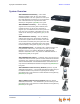
Synapse Installation Guide Back to Contents System Overview AT&T SB67010 PSTN Gateway — Each PSTN Gateway provides access to up to four analog outside telephone lines. The system can have up to four PSTN Gateways, supporting up to 16 telephone lines. Information that is only about the PSTN Gateway is designated by [PSTN] in this guide.
Synapse Installation Guide Back to Contents AT&T SB67050 Analog Terminal Adapter (ATA Optional) — The ATA allows the integration of non-Synapse devices, such as analog telephones, a fax machine, overhead paging equipment, and a music-on-hold source into the Synapse system. It also provides Group Mailboxes to allow different people to access the same Mailbox. The system can have only one ATA. Information that is only about the ATA is designated by [ATA] in this guide.
Synapse Installation Guide Installation Back to Contents To determine the SB67030/031 Deskset software version, press MENU, then 4. See the P Firmware version. To determine the software version of all installed devices, log in as administrator. See “Log in as Administrator” on page 80. Then click to see the software versions and other information. There may be a delay as the system gathers this information.
Synapse Installation Guide Back to Contents System Installation Overview Figure 1 illustrates how the Synapse system differs from conventional telephone systems in that calls are not coordinated by a central controller. Instead, the system uses a distributed control system over a new or existing LAN. Figure 1. Sample System Network A system must have at least one PSTN Gateway, one T1 Gateway, or one SIP Gateway.
Synapse Installation Guide Back to Contents System Installation Overview with Optional Analog Terminal Adapter If you have analog devices that you want to attach to the system, you will need an AT&T SB67050 Analog Terminal Adapter (ATA). The Synapse system supports one ATA per system. The ATA allows you to attach hardware such as conference phones, overhead paging equipment, a fax machine, or a source for Music On Hold (MoH) to Synapse.
Synapse Installation Guide Back to Contents System Installation Overview for Remote Sites If two separate Synapse systems both have SIP Gateways, then they can communicate with each other as “Remote Sites” on a privately managed network. Remote Sites allow users to make extension-to-extension calls between Synapse sites, thus avoiding long-distance charges.
Synapse Installation Guide Back to Contents Recommended Installation Sequence 1. Prepare your site for installation. See “Site Preparation” on page 26. 2. Install the Gateway(s). See “Gateway Installation” on page 35. 3. If you have only one Gateway, install the first Deskset. See “Deskset Installation” on page 38. This Deskset is assigned extension number 200 with no Direct Inward Dialing. 4.
Synapse Installation Guide Back to Contents See “System Configuration” on page 78 and the Synapse Administrator’s Guide at www.telephones.att.com/synapseguides. 10. Complete post-installation tasks. If you have set the system to use Call Appearance mode, ask all users to record their user names on their Desksets. See “Name Recording for the Auto Attendant Directory” in the Synapse Administrator’s Guide at www.telephones.att.com/synapseguides.
Synapse Installation Guide Back to Contents Planning Your System and Network Configuration This section describes several important configuration options that you should be aware of before you install the Synapse system. These options include Operation Mode (Call Appearance versus Line Appearance), IP addresses and connectivity, extension number assignments, analog bypass lines and analog telephones in the Synapse system.
Synapse Installation Guide Back to Contents IP Addresses and Connectivity An IP address is an individual numeric identification assigned to devices on a computer network. At least one Synapse device needs a network-assigned IP address on the subnet shared with any computers that will allow access to the WebUI. Valid IP addresses on the same subnet allow devices on the network to identify each other and enable communication.
Synapse Installation Guide Back to Contents SIP ALG (application-level gateway) functionality may be required if the SIP service provider does not use hosted NAT traversal. Extension Assignments The system assigns the first Deskset to join the network as extension 200. At this point you can use the Dial Plan Settings page in the WebUI to set a different first digit for extension numbers for Desksets that will be connected to the network. The WebUI calls this the Default Phone Extension Prefix.
Synapse Installation Guide Back to Contents Connecting Analog Devices to the ATA The ATA allows you to attach the following analog devices to the ports and jacks identified in Figure 23 on page 45. Most options require the system administrator to configure the feature in the WebUI. If you are planning to install more than one type of analog equipment, make sure there are suitable ATA ports available and configured.
Synapse Installation Guide Back to Contents Loud Ringers Loud Ringer devices must be connected to an FXS port assigned as Voice (default setting). Loud Ringers can be used for alerting users of an incoming call via a loud speaker and are treated within Synapse as a regular analog phone instead of OHP equipment. This type of overhead alerting can only be done by including the voice FXS port in a Ring Group.
Synapse Installation Guide Back to Contents Overhead Paging Overview You can set up either single or multi-zone external overhead paging (OHP), as shown in Table 2, but only one OHP system can be connected to the ATA. You can also use a loud ringer device, either on its own or with your existing OHP paging system, if supported. For more information, see “Loud Ringers” on page 19.
Synapse Installation Guide Back to Contents Even if the OHP has no RJ-11 jack, it may still have a Tip/Ring interface, requiring hard wiring. Whenever possible, try both the AUX OUT jack and an FXS port to find the best configuration for your needs. To install an OHP system, see “Connecting an Overhead Paging System (OHP)” on page 47. There are three possible OHP configurations.
Synapse Installation Guide Back to Contents Figure 6. Single-Zone Overhead Paging on FXS Port Multi-Zone Paging Broadcasts to speakers grouped into separate zones. Since the multi-zone OHP systems require zone selection, they cannot be combined into one zone together with Synapse Desksets. Multi-Zone OHP equipment connected to one of the FXS ports: When paging is configured as a multi-zone OHP, a dedicated Overhead Paging zone automatically appears as the last entry in the Deskset paging menu.
Synapse Installation Guide Back to Contents Verified Overhead Paging Devices Table 3 lists OHP systems that have been demonstrated to work with the Synapse System as of the publication of this document. More OHP systems may also have qualified for this list. For more information, call 1 (888) 916-2007. In Canada, dial 1 (888) 883-2474. Table 3.
Synapse Installation Guide Back to Contents ATA FXS 1 & FXS 2 FXS Door Phone Figure 8. Station Port (FXS) Door Phone Connection Trunk Port (FXO) Door Phone Support You can connect a Trunk Port (FXO) door phone to any one of the four Line (FXO) ports on a Synapse SB67010 PSTN Gateway as shown in Figure 9. The FXO door phone can be configured to call either a single extension or a group of extensions (a Ring Group). You can use the WebUI to configure an FXO door phone.
Synapse Installation Guide Back to Contents Tested Door Phone Models Table 4 lists door phones that have been demonstrated to work with the Synapse System as of the publication of this document. More door phones may also have qualified for this list. For more information, call 1 (888) 916-2007. In Canada, call 1 (888) 883-2474. Table 4.
Synapse Installation Guide Back to Contents Site Preparation This section describes how to prepare your site for a successful Synapse system installation. Network Requirements For more information on the network configuration, see “Planning Your System and Network Configuration” on page 15. A switched network topology is recommended for your LAN (using standard 10/100 Ethernet switches that carry traffic at a nominal rate of 100 Mbit/s). The office LAN infrastructure should use Cat.
Synapse Installation Guide Back to Contents Extremely low temperature Mechanical vibration or shock, such as on top of the washing machine or workbench. ATA Placement Considerations You can install the optional ATA near the Gateway, or near one of the third-party devices that are being used with it.
Synapse Installation Guide Back to Contents Assigning Telephone Lines and Extensions This section discusses various telephone line configuration issues to consider. Providing Limited Telephone Service During AC Power Outages PSTN Gateway The fourth line on each PSTN Gateway is a Bypass port that works during AC power failures. If you have a PSTN line plugged into LINE 4, connect a line-powered analog telephone to the RJ-11 jack labeled BYPASS for telephone service during power failures.
Synapse Installation Guide Back to Contents ATA Fax Line Configuration To support fax on the Synapse system, you should consider where the fax is, and which telephone line will be used for incoming faxes. Fax line configuration for the Synapse system differs depending on whether you are using a PSTN Gateway or a T1 or SIP Gateway. For more information about fax configuration and ATA configuration, see the Synapse Administrator’s Guide at www.telephones.att.com/synapseguides. Figure 10.
Synapse Installation Guide Back to Contents delay, the ringback tone generated by the CO (Central Office) is no longer heard by the caller. Instead, the caller hears the ringback tone generated by the Gateway. For outgoing calls, the caller ID of the fax number may be sent instead of the primary business telephone number. If the recipient returns a missed call via their caller ID log, the caller will then experience the eight-second delay mentioned above.
Synapse Installation Guide Back to Contents Gateway and ATA Placement You can place the Gateway or ATA on a tabletop, mount it into a standard 19-inch metal rack, or wall mount it. The PSTN Gateway must be installed within three feet of the building ground point. Install each device using the following instructions. Rack Mounting To mount the Gateway or ATA into a standard 19-inch rack: 1. Remove the two mounting brackets and six screws from the packing tissue. 2.
Synapse Installation Guide Back to Contents 6. Insert a top mounting screw (not included) in one side and turn it several turns to establish support. Repeat for the other side. 7. Tighten the screws. Wall Mounting You can mount the Gateway or ATA to a wall using the two mounting slots on the bottom of the device. Ensure that the device is oriented as shown in Figure 11 to allow air to flow vertically through the ventilation holes on each side of the device. Figure 11.
Synapse Installation Guide Back to Contents Grounding The SB67010 PSTN Gateway, SB67060 T1 Gateway, SB67070 SIP Gateway, and the SB67050 Analog Terminal Adapter must be connected to reliable earth ground. The connection to earth ground must be verified by qualified personnel. The SB67010 PSTN Gateway must be connected to reliable earth ground using the supplied ground wire connected to a terminal on the back of the Gateway chassis.
Synapse Installation Guide Installation Back to Contents 5. Tighten the screw. 6. Connect the other end of the grounding cable to the building ground point, usually located at the electrical breaker box.
Synapse Installation Guide Back to Contents Gateway Installation To install the Gateway: 1. Install a Gateway first. Plug the AC plug into an electrical outlet not controlled by a wall switch and the DC plug into the DC jack, as shown in Figure 14. Wait up to one minute until the screen lights up. 2. Plug a gray Cat.-5 LAN cable for the PSTN Gateway or SIP Gateway or yellow Cat.-6 LAN cable for the T1 Gateway into the Ethernet port marked LAN. Use the supplied cables or a comparable substitute.
Synapse Installation Guide Back to Contents For more information, see the Synapse Administrator’s Guide at www.telephones.att.com/synapseguides. To connect the PSTN Gateway telephone lines: 1. Remove the plastic covers from the Gateway PSTN (telephone) jacks to be used, marked LINE 1 through LINE 4 and BYPASS, as shown in Figure 16. PSTN Line LEDs LINE 1 through LINE 4 LINE 1 LINE 1 LINE 2 LINE 3 LINE 4 BYPASS BYPASS LINE 2 LINE 3 LINE 4 POWER UP DC 5.
Synapse Installation Guide Back to Contents To connect the T1 Gateway T1 cable: Plug the black T1 cable into the Gateway T1 Port, as shown in Figure 18, and into your T1/PRI network device from your service provider. T1 Status Indicators T1 Port Figure 18. T1 Gateway Line Connections Do not make any calls until the POWER and the SYN/ACT LEDs are green. See “T1 Gateway Features” on page 59. The SB67060 T1 Gateway must use only No.26 AWG or larger Telecommunications line cord to reduce the risk of fire.
Synapse Installation Guide Back to Contents Deskset Installation Figure 19 identifies the features on the bottom and side of the Deskset. You can install the Deskset on a desktop or mount it on a wall. Figure 19 represents the SB67030/031 Deskset. Although the SB67020 Deskset is slightly different, its features have the same basic layout. The SB67031 Deskset is compatible only with Synapse systems with software version 1.9.5 and later. Ensure you have upgraded your system to software version 1.9.
Synapse Installation Guide 5. Corded Headset Jack Back to Contents Actual jack location may be different than shown 6. Corded Handset Jack 7. Wall-Mount Slots See “To install the Deskset on a wall:” on page 42. To attach the Desktop Stand for desktop installation: 1. Select a Deskset position. The desktop setup requires the Deskset Stand and provides two positions, Option 1 at 45° and Option 2 at 60°, as shown in Figure 20.
Synapse Installation Guide Back to Contents Flexible tabs Option 1 Solid tabs Flexible tabs Solid tabs Option 2 Figure 22. Deskset Stand Installation 5. Rotate the stand away from you until it rests against the base and you hear a click as the flexible tabs lock into place. To rotate the Handset tab for wall and Deskset Option 2 installation: 1. Press the switch hook and slide the Handset Tab toward the top of the base, as shown. Switch hook Handset Tab Installation 2.
Synapse Installation Guide Back to Contents “Hook” To connect the Cat.-5 LAN cable to the Deskset: With a PC: If there is a networked computer and no extra Ethernet wall jacks near the Deskset, then plug the PC Ethernet cable into the Deskset so the Deskset and PC share the same network connection. 1. Unplug the Cat.-5 Ethernet cable from your computer. 2. Plug that Cat.-5 Ethernet cable into the Network port on the back of the Deskset, as shown below. Network PC 3. Plug another Cat.
Synapse Installation Guide Back to Contents Without a PC: If the Deskset has a dedicated network connection, then connect the Deskset to the network connection only. 1. Plug a Cat.-5 Ethernet cable into the Network port on the back of the Deskset. 2. Plug the other end into the Ethernet wall jack. To connect power: [020/031] If you are using PoE, connecting the Deskset to the network also connects the power. If you are using the supplied power adapter: 1.
Synapse Installation Guide Back to Contents Wall-Mount Screws Installation 5. Plug the Ethernet cable into the wall jack. 6. Plug the power adapter into a power outlet not controlled by a wall switch. Skip this step if using PoE. 7. Make sure the Handset tab is in Wall position, as described in “To rotate the Handset tab for wall and Deskset Option 2 installation:” on page 40. 8. Connect the corded handset to the handset jack on the left side of the Deskset.
Synapse Installation Guide Back to Contents To connect the corded handset and an optional corded headset: Connect the corded handset: 1. Plug the coiled end of the handset cord into the handset jack on the left side of the Deskset. Handset Jack On Deskset Handset Jack on Handset 2. Plug the end of the handset cord with the longer straight portion into the handset, then hang up.
Synapse Installation Guide Back to Contents SB67050 ATA Installation To install the ATA: 1. After installing at least one Deskset, plug the AC plug into an electrical outlet not controlled by a wall switch and the DC plug into the DC jack, as shown in Figure 23. Wait up to one minute until the screen lights up. To prevent the loss of ATA-supported services during power outages, plug the AC power plug into an Uninterruptible Power Supply (UPS). 2. Plug a Cat.-5 Ethernet cable into the port marked LAN.
Synapse Installation Guide Back to Contents ATA Analog Telephone/ Conference Phone Analog Telephone/ Conference Phone Figure 24. ATA Analog Telephone Connections Connecting a Fax Machine To install a fax machine: 1. Remove the plastic covers from the FXS 1 or FXS 2 (telephone) port to be used on the ATA. 2. Plug a telephone line from the fax machine into the ATA FXS 1 or FXS 2 port, as shown in Figure 25. 3. Configure the fax connection in the WebUI.
Synapse Installation Guide Back to Contents Connecting an Overhead Paging System (OHP) A Single Zone or Multi-Zone system can be integrated into an existing Synapse network. The control unit or analog amplifier for the Overhead Paging system connects directly to the ATA via an FXS or the AUX OUT jack, depending on the type of paging system. Synapse supports most OHP systems that support PBX station ports or auxiliary audio-out connections to a PBX.
Synapse Installation Guide Back to Contents To install an overhead paging system: 1. Remove the plastic cover from the FXS 1 or FXS 2 port to be used on the ATA. 2. Plug the telephone line from the OHP device into the FXS 1 or FXS 2 port, or plug an audio cable from the OHP device into the ATA AUX OUT port, as shown in Figure 23 on page 45, depending on the requirements of the paging system.
Synapse Installation Guide Back to Contents Connecting a Music on Hold Source To install a music on hold source: 1. Use the supplied auxiliary audio cable to plug a streaming audio source, such as a radio or MP3 music player, into the ATA AUX IN port as shown in Figure 27. If the supplied cable does not connect to your music source, use another cable that will connect your device to the 3.5 mm AUX IN port. This audio source must have a volume control.
Synapse Installation Guide Back to Contents SB67040 Cordless Handset Installation The SB67040 Cordless Handset requires registration to an SB67030/031 Deskset. The SB67020 Deskset does not support the SB67040 Cordless Handset. The SB67040 Cordless Handset is not supported when the system is in Line Appearance mode. Charger Installation Place the Handset in the charger when not in use. To plug the Handset charger into AC power: Installation 1.
Synapse Installation Guide Back to Contents Battery Installation The Cordless Handset uses a rechargeable 2.4v nickel-metal hydride cell (NiMH) battery pack. To install the Handset battery: 1. Remove the battery cover by pressing and sliding the cover downward. Color-Coded Battery Connector 2. Plug the battery connector securely into the plug inside the Handset battery compartment, matching the color-coded label. Use only the supplied rechargeable battery or replace it with battery model BT8001.
Synapse Installation Guide Back to Contents Battery Charging Charge the Handset battery for at least 16 hours before use. When fully charged, the Handset battery provides approximately five hours of talk time or three days of standby time. To charge the Handset battery: Place the Handset in the charger, as shown. The CHARGE light is on when the Handset is charging. CHARGE light If the Handset has not yet been registered, the Register screen appears within 15 seconds. 12:00a Jan.
Synapse Installation Guide Back to Contents TL7600 Cordless Headset Installation The TL7600 Cordless Headset requires registration to an SB67030/031 Deskset. The SB67020 Deskset does not support the TL7600 Cordless Headset. Charger Installation To install the TL7600 charger: 1. Plug the small end of the charger power adapter into the jack on the underside of the charger, then route the cord through the slot. Power Jack 2.
Synapse Installation Guide Back to Contents Battery Installation Install the battery as shown below. For optimal performance, charge the Headset battery for at least six hours before use. When not in use, recharge the Headset by returning it to the Headset charger. To install a battery: 1. If the battery door is attached, press on both sides of the battery compartment cover and lift the cover up and off as shown. 2. Insert the battery into the battery compartment with the label THIS SIDE UP facing up.
Synapse Installation Guide Back to Contents Battery Charging After installing the battery, charge the Headset by placing it in the Headset charger as shown below. Before registration, the Headset ON/OFF light flashes twice every five seconds whether the Headset is charging or not. After registration, the Headset ON/OFF light is on when the Headset is charging. To charge the battery: 1. Insert the Headset into the charger as shown. 2. Push the Headset downward until the Headset ON/OFF light turns on.
Synapse Installation Guide Back to Contents C HAPTER 2 GETTING STARTED This chapter gets you started with configuring the Synapse system from the devices. Most of these functions are duplicated in the easier-to-use WebUI described in the next chapter, but if you need to assign static IP addresses, they must be set at each device. You can only directly reset a device from the device, although some functions in the WebUI include device resets.
Synapse Installation Guide Back to Contents PSTN Gateway Features Figure 28 illustrates the PSTN Gateway features and connections. LINE 1 LINE 1 1 LINE 3 LINE 4 BYPASS DC 5.1V LAN RESET LINE 3 LINE 4 POWER UP LINE 2 LINE 2 DOWN SELECT - 2 CANCEL 3 4 5 + 6 Figure 28. PSTN Gateway Features and Connections 1. Display Provides system and network status, device information, and configuration data. See “Gateway Front Panel Interface” on page 63. 2.
Synapse Installation Guide Back to Contents Figure 29 and Table 5 provide an illustration and description of the PSTN Gateway front panel. Status LEDs Power LED Menu Navigation Keys Figure 29. PSTN Gateway Front Panel Table 5. PSTN Gateway Front Panel Keys and LEDs Key Used To: LED Navigate through the menus, and to increase/decrease editable fields. Highlight the previous or next item in the list.
Synapse Installation Guide Back to Contents T1 Gateway Features Figure 30 illustrates the T1 Gateway features and connections. 1 2 3 4 5 Figure 30. T1 Gateway Features and Connections 1. Display Provides system and network status, device information, and configuration data. See “Gateway Front Panel Interface” on page 63. 2. Reset When pressed momentarily, restarts the Gateway. When pressed and held for more than five seconds and with the LAN cable not connected, restores factory defaults. 3.
Synapse Installation Guide Back to Contents Figure 31 and Table 6 provide an illustration and description of the T1 Gateway front panel. Status LEDs Power LED Menu Navigation Keys Figure 31. T1 Gateway Front Panel Table 6. T1 Gateway Front Panel Keys and LEDs Key Used To: Navigate through the menus, and to increase/decrease editable fields. Highlight the previous or next item in the list.
Synapse Installation Guide Back to Contents SIP Gateway Features Figure 32 illustrates the SIP Gateway features and connections. 1 2 3 4 5 Figure 32. SIP Gateway Features and Connections 1. Display Provides system and network status, device information, and configuration data. See “Gateway Front Panel Interface” on page 63. 2. Reset When pressed momentarily, restarts the Gateway. When pressed and held for more than five seconds and with the LAN cable not connected, restores factory defaults. 3.
Synapse Installation Guide Back to Contents Figure 33 and Table 7 provide an illustration and description of the SIP Gateway front panel. Status LEDs Power LED Menu Navigation Keys Figure 33. SIP Gateway Front Panel Description Table 7. SIP Gateway Front Panel Keys and LEDs Key Used To: Navigate through the menus, and to increase/decrease editable fields. Highlight the previous or next item in the list.
Synapse Installation Guide Back to Contents Gateway Front Panel Interface You can access basic information and perform some configuration tasks using the Gateway’s front panel. Most of these tasks are easier to do using the WebUI. See “WebUI Overview” on page 79. The Gateway displays the Idle screen after completing the power-up sequence. Use the Gateway Main menu to perform some system operations.
Synapse Installation Guide Press Back to Contents to return to the Main Menu. Gateway Configuration Press / in the Gateway Main menu until Configuration is highlighted, as shown in Figure 36, and press to display the Configuration menu. The current setting is indicated with [x]. Figure 36. Gateway Configuration Configuration — Current Gateway settings. Getting Started Auto IP — Is set automatically. Static IP — You can change the static IP only from the Gateway.
Synapse Installation Guide Back to Contents Upgrade Gateway Software If you have system settings that you want to retain, back up the settings before upgrading the system software. To upgrade the Gateway software to the latest version: in the Gateway Main menu until Configuration is to display the Configuration menu. 1. Press / highlighted and press 2. Press to highlight Upgrade Software and press to initiate the software upgrade process.
Synapse Installation Guide 4. Getting Started Back to Contents If the upgrade process is interrupted by removing the server connection, no restart occurs. The Gateway remains on the xx% complete screen, until an action is taken at that Gateway. The process does not resume even after the server connection is reestablished. Pressing during the programming process terminates the download midstream and returns you to the Configuration menu. The previous software version remains in effect.
Synapse Installation Guide Back to Contents ATA Features When the ATA is first connected to your LAN, the two FXS ports are configured as POTS phone lines and assigned the next available extension numbers. ATA extension numbers do not appear in the Extension list on Deskset screens. They do, however, appear on Call Logs, Redial lists, and Message lists. The two ATA extensions do not count toward the 100-extension limit of the Synapse system.
Synapse Installation Guide Back to Contents Figure 38 and Table 8 provide an illustration and description of the ATA front panel. Status LEDs Power LED Menu Navigation Keys Figure 38. ATA Front Panel Description Table 8. ATA Front Panel Keys and LEDs Key Used To: Navigate through the menus, and to increase/decrease editable fields.
Synapse Installation Guide Back to Contents ATA Front Panel Interface You can access basic information and perform some configuration tasks using the ATA front panel. These tasks are easier to do using the WebUI. See “WebUI Overview” on page 79. The ATA displays the Idle screen after powering up. Access the ATA Main menu to perform the system operation functions. 30 )HE $7$ 6\QFKURQL]HG ,3 Figure 39.
Synapse Installation Guide Back to Contents ATA Configuration Press / in the ATA Main menu until Configuration is highlighted, as shown in Figure 41, and press to display the Configuration menu. The current setting is indicated with [x]. You can use this interface or the WebUI to upgrade software. Figure 41. ATA Configuration Configuration — Current ATA settings: Auto IP — Is set automatically. Static IP — You can change the Static IP only from the ATA.
Synapse Installation Guide Back to Contents If the host is found, but there is no new software available, then the No New Version message appears. If the device is sluggish or unresponsive during the upgrade process, see “A Synapse device becomes sluggish or unresponsive during or immediately after software upgrade.” on page 117. 3. If new software is available, you are prompted to initiate the upgrade by pressing , or abort by pressing .
Synapse Installation Guide Back to Contents Resetting Devices You may need to manually restart a device or return a device to factory defaults (see “Appendix B: Default Settings” on page 146). To reset a device, press the RESET button shown in Figure 42 and Figure 43 on page 73 by inserting a pen or paper clip into the hole and applying pressure to the button. The T1 Gateway, SIP Gateway, and ATA (not shown) have a RESET button in the same location on the front panel as the PSTN Gateway.
Synapse Installation Guide Back to Contents Reset Button Figure 43.
Synapse Installation Guide Back to Contents Deskset IP Settings Synapse devices are connected to a LAN so they can communicate with each other. See “System Installation Overview” on page 10 and “IP Addresses and Connectivity” on page 16 for a discussion of the Synapse network configuration and IP settings. To display the IP Settings screen: 1. Access the Admin Settings menu: Press MENU, then press 3 on the dial pad, then enter the Admin password (12345 is the default password), and press SELECT. 2.
Synapse Installation Guide Back to Contents IP Settings 1. IP Configuration Auto 2. Set/Edit Static IP 3. IP Status Use Use or or to mov e highlight. to cy cle through options. IP Configuration Set IP to: Auto Quick Dial Save Save 030/031 Deskset IP Configuration 3. Press Save 020 Deskset IP Configuration to accept the changes and return to the Admin Settings menu. Set/Edit Static IP If your business requires a static IP address, contact your network administrator.
Synapse Installation Guide Back to Contents IP Status This screen is for informational purposes only. To view the IP status: 1. Access the Admin Settings menu: Press MENU, then press 3 on the dial pad, then enter the Admin password, and press SELECT. 2. Press 3 on the dial pad. The IP Settings screen appears. 3. On the IP Settings screen, press 3. The IP Status screen appears. IP Status Auto 192.168.0.123 255.255.255.0 192.168.0.1 00:11:A0:00:12:8D Connected Connected 192.168.0.134 to scroll.
Synapse Installation Guide Back to Contents Upgrade Deskset Software To access the Deskset Software Upgrade feature: 1. Access the Admin Settings menu: Press MENU, then press 3 on the dial pad, then enter the Admin password, and press SELECT. 2. Press 5. The Software Upgrade screen appears. The system scans for an upgrade. Software Upgrade Scanning for Upgrades...
Synapse Installation Guide Back to Contents CHAPTER 3 SYSTEM CONFIGURATION You can configure the Synapse System using the WebUI. The WebUI consists of web pages with editable settings for the system and each Synapse device. The WebUI is embedded in every SB67010 PSTN Gateway, SB67020 Deskset, SB67030/031 Deskset, and optional SB67050 Analog Terminal Adapter (ATA). When you access the WebUI, you are accessing it on the device, not on the Internet.
Synapse Installation Guide Back to Contents WebUI Overview If two Synapse devices are connected to the LAN, and as long as one Synapse device is currently on the same subnet as a PC, you can use the WebUI to administer the system. Only one person should log in as system administrator at a time to prevent accidentally overwriting and losing intended changes.
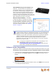
Synapse Installation Guide Back to Contents Log in as Administrator To access the browser interface and log in: 1. Ensure your computer is connected to the same IP subnet as the Synapse system. You can connect your computer to the PC port on the back of a Deskset. 2. On the Deskset, press MENU then 4. The Deskset Information screen appears.
Synapse Installation Guide 6. Back to Contents Enter admin in the Login Name field and 12345 in the Password field, then click . You may change the Admin ID and password once you are logged in. The System Information page appears. Click topics from the navigation menu on the left side of the WebUI to see them. You view and change settings in two different types of fields: drop-down lists and entry fields into which you type information.
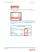
Synapse Installation Guide Back to Contents Error Handling If you type an invalid value into one of the WebUI fields and click , the page is not saved. The WebUI displays an error message at the top of the page. The field with the incorrect value is highlighted in yellow, as shown in Figure 45. You can view a more detailed error description by resting your mouse pointer on the highlighted field. . Error Message Invalid Entry Figure 45.
Synapse Installation Guide Back to Contents System Settings When making changes to the System Settings through the WebUI, ensure that no one is using the system. You might need to make the changes after normal office hours. The WebUI settings available to you vary according to the system configuration. T1, SIP, and ATA settings and features are only available and visible in the WebUI when those devices are installed.
Synapse Installation Guide Back to Contents and SIP Gateway use the Direct Inward Dial (DID) data from your Telephone Service Provider to automatically route incoming calls. See “Direct Inward Dial” in the System Administrator’s Guide. Trunk Naming Name the system trunks for easier identification. For PSTN Gateways, you can assign names to all lines—up to 16, depending how many PSTN Gateways are installed. For the T1 Gateway, there is only one physical trunk, so only that one trunk can be named.
Synapse Installation Guide Back to Contents Configuring a Trunk Port (FXO) Door Phone You can configure a Trunk Port (FXO) door phone as described in “Trunk Port (FXO) Door Phone Support” on page 24 using several different WebUI pages. The procedure varies depending on whether the system is in Call Appearance mode or Line Appearance mode.
Synapse Installation Guide Back to Contents b. On the Trunk Naming page, select the trunk (PSTN Gateway port) for which you enabled Door Phone Mode in Step 1. c. Give this trunk a name such as “Door” or “Entry”. 3. Click 4. Reserve the trunk that the door phone will use. Doing this will prevent other Desksets from seizing the door phone line for outside calls. 5. . a. In the navigation menu at left, click Trunk Reservation. b.
Synapse Installation Guide 6. Back to Contents b. In the Select Trunk list, select the door phone trunk. c. In the Route Call to list, select the extension or Ring Group that you want the door phone to ring. Click . To configure a trunk port (FXO) door phone (Line Appearance mode): 1. Enable Door Phone Mode. a. In the navigation menu at left, click Device Management, then Device Log. b. In the Device Log list, select the PSTN Gateway that will connect to the door phone. c.
Synapse Installation Guide 2. 3. Back to Contents Name the trunk that the door phone will use. a. In the navigation menu at left, click System Settings, then Trunk Naming. b. On the Trunk Naming page, select the trunk (PSTN Gateway port) for which you enabled Door Phone Mode in Step 1. c. Give this trunk a name such as “Door” or “Entry”. Because this name appears on SB67030/031 Deskset screens, names should be four to six characters in length. Click .
Synapse Installation Guide Back to Contents Select the door phone trunk, or select None to assign it to other PFKs or disable door phone access for this Deskset. Figure 46. SB67030/031 Deskset PFKs Select the door phone trunk, or select None to assign it to other PFKs or disable door phone access for this Deskset. Figure 47.
Synapse Installation Guide Back to Contents Line Calibration Configuration If your system uses Centrex lines, you must enter an outbound line prefix or code in order for line calibration to take place. You should perform this procedure before connecting the lines to the PSTN Gateway. Consult your Centrex line provider for the correct code to enter. Centrex lines operate in Line Appearance mode only. To enter Centrex line access codes: 1.
Synapse Installation Guide Back to Contents Updating Devices New software versions improve system functionality. All Gateways, the optional ATA, and all Desksets should be running the same software version number. (The optional Cordless Handsets and Cordless Headsets have different software version number sequences.) You can update all devices with one command, or you can update the Synapse devices individually. AT&T recommends automatic device software upgrades for installations with Internet access.
Synapse Installation Guide Back to Contents To update all devices to the latest software version: 1. In the navigation menu at left, click Device Management, then Update Device. The Update Device page appears. 2. At the bottom of the page, press . The system looks on the Internet for the latest software and systematically updates and then restarts each device. All calls are dropped. A caution appears to remind you that all devices will be restarted as each is updated.
Synapse Installation Guide Back to Contents To update a single device to the latest software version: 1. In the navigation menu at left, click Device Management, then Update Device. 2. In the Update Device list, select a Gateway, ATA, or Deskset to update. The Current Software Version for that device appears. You can only update one device at a time. Only the selected device is updated. 3. Click .
Synapse Installation Guide Back to Contents Product Registration In order to keep your system up to date with the latest upgrades and ensure timely warranty support, it is extremely important to register your system. To register a device, you need its MAC address. To find a Deskset MAC address: For Desksets, at the Desksets, press MENU, then press 4. Note the MAC Address line.
Synapse Installation Guide Back to Contents CHAPTER 4 TROUBLESHOOTING If you have difficulty operating your system, try the following suggestions in this section: “Common Troubleshooting Procedures” on page 96 “Initial Installation” on page 105 “Display Messages” on page 106 “WebUI” on page 112 “PC/Deskset Interaction” on page 119 “Other Deskset Features” on page 120 “SB67050 Analog Terminal Adapter” on page 123.
Synapse Installation Guide Back to Contents Common Troubleshooting Procedures Follow these procedures to resolve common issues. Resetting Devices You may need to manually restart a device or return a device to factory defaults (see “Appendix B: Default Settings” on page 146). To reset a device, press the RESET button shown in Figure 48 on page 97 and Figure 49 on page 97 by inserting a pen or paper clip into the hole and applying pressure to the button.
Synapse Installation Guide Back to Contents LINE 1 LINE 1 LINE 2 LINE 3 LINE 4 BYPASS LINE 2 LINE 3 DC 5.1V LAN RESET LINE 4 POWER UP DOWN SELECT - + CANCEL Reset Button Figure 48. PSTN Gateway Reset Button Reset Button Figure 49. Deskset Reset Button Resolving General Functional Issues To resolve a blank screen or device that does not work at all: Ensure the AC plug is plugged into an electrical outlet not controlled by a wall switch. Verify that the AC power outlet has power.
Synapse Installation Guide Back to Contents To resolve an incorrect system clock: If the system clock displays the wrong time, the system lacks Internet access for acquiring current time data. 1. Log on to the WebUI as administrator and click System Basic Settings. 2. In the System Time/Date Options section, specify a local Network Time Protocol (NTP) Server, or manually set the time. Then click .
Synapse Installation Guide Back to Contents To restore a Deskset to factory defaults: To restore a Deskset to factory defaults, insert a pen or paper clip into the reset hole on the bottom of the Deskset (as shown in Figure 50) and press the RESET button for more than five seconds. Figure 50. Deskset Reset Button To resolve problems with a cordless device: For features or audio problems, make sure that the Deskset associated with the cordless device does not share the problem. 1. 2.
Synapse Installation Guide Back to Contents Resolving Audio Echoes (PSTN Gateway) The SB67010 PSTN Gateway uses automatic telephone line calibration to ensure optimal audio performance on outside calls. If excessive echo occurs on outside calls consistently, observe the Gateway line calibration data to understand any telephone line issues. Occasional echoes may be caused by the other person’s phone. To resolve audio echo issues: 1. Log on to the WebUI as administrator.
Synapse Installation Guide Back to Contents Resolving General Audio Issues Check the following if you hear static, sudden silences, gaps in speech, echoes, distorted speech, or garbled speech. To resolve general audio issues: You may be experiencing network problems. Your LAN administrator should ensure the following minimum guidelines are met: A switched network topology, which requires attaching network components to switches rather than hubs, is recommended.
Synapse Installation Guide b. Back to Contents Select the extension from the Select Extension to Back up drop-down list, and click to save the file to a specified location on your computer. You will need to locate and retrieve this file later, so make sure you remember where you saved it. The default file name will be in the format: backup_ds_[extension number]_[year]-[month]-[day]_[time].cfg.
Synapse Installation Guide Back to Contents Reintroducing a Gateway or ATA Into the System If there are no more than five Gateways in the system (four PSTN Gateways and one T1 Gateway), and a Gateway or ATA screen displays Synch Failed or Synchronizing for more than a few minutes, you may need to remove the Gateway or ATA from the system and reintroduce it.
Synapse Installation Guide Back to Contents Power Failure Recovery Procedure The Synapse system automatically recovers after a power failure. The following describes the recovery process. Allow about a minute for the Gateways and ATA to boot up when power returns after a power failure. The power-up sequence for the Gateways and ATA follows: 1. About 20 seconds after turning on power to the device, the POWER LED turns on. 2.
Synapse Installation Guide Back to Contents Initial Installation The device screen displays Synchronizing. Troubleshooting Probable Cause Corrective Action The device has previous data and settings that are now inconsistent with current system settings. Erase all Deskset data and settings by unplugging the LAN cable and pressing the reset button on the bottom of the Deskset for more than five seconds.
Synapse Installation Guide Back to Contents Display Messages The Gateway screen is blank. Probable Cause Corrective Action Many. See “To resolve a blank screen or device that does not work at all:” on page 97. The Gateway screen displays Joining Site... for more than one minute. Probable Cause Corrective Action The Gateway is failing to synchronize with a Deskset configured for a different system configuration.
Synapse Installation Guide Back to Contents Probable Cause Corrective Action The device was configured on another network or has returned to the system after being deleted from the system. Reset to factory defaults by using a paper clip to press and hold the RESET button for more than five seconds. See “Reintroducing a Deskset Into the System” on page 101 or “Reintroducing a Gateway or ATA Into the System” on page 103. The maximum number of that type of device has been reached.
Synapse Installation Guide Back to Contents Deskset cannot make or receive phone calls and the Deskset screen displays Synchronizing. Probable Cause Corrective Action The Deskset may have an incompatible software version. Log on to the WebUI using the IP address of the Deskset and update the software. See “Updating Devices” on page 135. A Synapse device displays Host Not Found after a user attempts a software upgrade.
Synapse Installation Guide Back to Contents T1 Gateway Indicators I cannot make or receive phone calls and the T1 Gateway SYN/ACT LED is GREEN. Probable Cause Corrective Action There are no T1 channels available to make the call. Check the T1 trunk configuration. a. Log on to the WebUI as administrator, click System Settings, then T1 Settings. b. Verify that Number of Voice Channels and Lowest Voice Channel have been configured correctly according to your T1 service. c.
Synapse Installation Guide Back to Contents I cannot make or receive phone calls and the T1 Gateway RAI/LOF/LOS LED is flashing RED. Probable Cause Corrective Action The Flashing Red alarm indicates Loss of Signal 1. Verify that your T1 cable is connected to the equipment. There is loss of valid signal from the service provider. 2. Check the T1 Settings to confirm that the configuration parameters (Signaling type, Build out) correspond to the service provider's. 3.
Synapse Installation Guide Back to Contents I cannot make or receive phone calls and the T1 Gateway SYN/ACT LED is OFF and RAI/LOF/LOS LED is RED. Probable Cause Corrective Action The T1 Gateway is not synchronized with the T1 service. Check the correct T1 cable is used and that it is properly connected to the T1 Gateway. PSTN Gateway Setup Line-Status LEDs do not flash red when the telephone line cords are plugged into the Gateway after power is switched on.
Synapse Installation Guide Back to Contents WebUI Administrator WebUI The WebUI is unresponsive. Probable Cause Corrective Action The web browser encountered an unexpected problem. 1. Close the unresponsive web browser, reopen the browser, and log back in as administrator. 2. If this does not work, try again using the IP address of a Deskset that is connected to the PC you are using. 3. If this does not work, try closing the browser and waiting 10 minutes before logging back in.
Synapse Installation Guide Back to Contents A Synapse device upgrade failed, the WebUI displays “Login to target device failed”, and the WebUI and device screens display the old software version. Probable Cause Corrective Action The software version of the device you are currently logged into is no longer compatible with the software version of other devices within the network. 1.
Synapse Installation Guide Back to Contents Some devices did not update after using . Probable Cause Corrective Action Did not allow enough time for software to update due to a slow Internet connection. Wait 30 minutes, then check whether additional devices have been updated. If devices are still being updated, then the Internet connection is slow and you must wait for all the devices to complete the update process. If the update has failed (you see a failure message), retry .
Synapse Installation Guide Back to Contents An extension number was not changed correctly. Probable Cause Corrective Action That extension may have been on a call while the extension number was changed in the WebUI, or someone tried to change the extension number to a number that was already being used. Change the extension number again. Make sure no one is using that extension while you are changing its settings. a.
Synapse Installation Guide Back to Contents Changes made to the T1 Settings WebUI page do not change the system. Probable Cause Corrective Action Clicking alone may not perform the needed reset of the T1 Gateway. After you make changes to the T1 Settings WebUI page and click , press the T1 Gateway RESET button for less than five seconds or remove and restore AC power to the T1 Gateway. Pressing the RESET switch for more than five seconds will erase all data and settings.
Synapse Installation Guide Back to Contents My hold announcement is cut off. Probable Cause Corrective Action Hold announcements in later versions of Synapse are limited to two minutes. Record your hold announcement again. Keep it under two minutes in length. System Upgrade A Synapse device becomes sluggish or unresponsive during or immediately after software upgrade. Probable Cause Corrective Action Cannot connect to AT&T server or the device encountered an unexpected problem.
Synapse Installation Guide Back to Contents User WebUI Unable to access the WebUI Log-in page from my computer. Probable Cause Corrective Action The computer is not connected to the same subnet (network) as the Deskset, and the subnets are not set up to communicate. Verify the IP address. You must correctly enter the IP address of your Deskset into your Internet browser’s address bar. At the Deskset, press MENU –> 4 to see the IP address displayed in the third line of the information.
Synapse Installation Guide Back to Contents PC/Deskset Interaction Internet connection or access to the local network on my computer does not work after installing the Deskset. Probable Cause Corrective Action The Ethernet cords are not installed correctly. Check that the Ethernet cord from the computer is plugged into the Deskset port labeled .A second Ethernet cord should be plugged into the Ethernet port on the Deskset marked with the other end plugged into your LAN.
Synapse Installation Guide Back to Contents Other Deskset Features For more information about the corrective actions recommended in this troubleshooting section, see the SB67030/031 Deskset and Accessories User’s Guide and SB67020 Deskset User’s Guide at www.telephones.att.com/synapseguides. Other Desksets do not appear in the extension list. Probable Cause Corrective Action The Deskset is not connected to the same subnet as the other Desksets.
Synapse Installation Guide Back to Contents My Deskset soft keys have changed. Probable Cause Corrective Action The highlight bar has moved to another line on the screen. The soft keys reflect the call state and Deskset functions. They change depending on which line is highlighted. For example, there may be a held call, an active call, or an incoming call on the screen. To view the soft keys for that call, move the highlight bar by pressing or . I am unable to add an entry to Quick-Dial list.
Synapse Installation Guide Back to Contents I am unable to locate the Cordless Handset from the SB67030/031 Deskset. Probable Cause Corrective Action The Cordless Handset’s battery is dead. Charge the Cordless Handset battery. The Cordless Handset is out of range or not registered. If does not appear on the Deskset Idle screen, then the Cordless Handset is not registered. Register the Handset at the Deskset. Press MENU –> 2 –> 6 –> 1 –> .
Synapse Installation Guide Back to Contents SB67050 Analog Terminal Adapter General Troubleshooting ATA does not work at all. The Power LED is off. Probable Cause Corrective Action There is no power to the device. Ensure the AC plug is plugged into an electrical outlet not controlled by a wall switch. Verify that the AC power outlet has power. Plug in a lamp. If the lamp won’t light, contact an electrician or use another power outlet.
Synapse Installation Guide Back to Contents ATA is not active immediately after a power interruption. Troubleshooting Probable Cause Corrective Action The ATA needs time to restore service. Allow at least 30 seconds for the ATA to boot up again after a power failure.
Synapse Installation Guide Back to Contents Music on Hold (MoH) Music on Hold (MoH) is not playing and the AUX IN LED is OFF. Probable Cause Corrective Action MoH is disabled. Log in to the WebUI as administrator, click System Settings, then Hold Settings. Set Select Port to be ATA: AUX IN and then click . MoH is not playing and the AUX IN LED is solid RED, but MoH is enabled in the WebUI.
Synapse Installation Guide Back to Contents MoH is not playing and the AUX IN LED is GREEN. Probable Cause Corrective Action MoH not properly configured. Verify that the audio source is playing and not muted. Set the MoH output volume level by adjusting the playback volume of the music source device connected to the ATA. You may need to set the volume near the maximum. Some MoH sources without volume controls, such as those with audio-out jacks, are usually very loud and might be too loud.
Synapse Installation Guide Back to Contents MoH audio is too quiet, fluctuating, or dropping out. Probable Cause Corrective Action The volume on the audio source is too low or too high. If the volume is too high, overdriving the audio components may be causing short periods of sound to drop out (not be heard).
Synapse Installation Guide Back to Contents Overhead Paging (OHP) OHP General Troubleshooting Overhead paging (OHP) is not working. Probable Cause Corrective Action You don’t know whether your OHP is single- or multi-zone and whether it needs an FXS or an Audio-Out connection. The OHP may not be properly installed. There are three possible configurations for OHP: Single-zone paging connected to the AUX OUT jack. Single-zone paging connected to one of the two FXS ports.
Synapse Installation Guide Back to Contents I cannot add a multi-zone Paging Zone to other Paging Zones. Probable Cause Corrective Action Multi-zone paging does not allow a combination of OHP equipment and Desksets within one Paging Zone. Page multi-zone OHP zones separately from extensions. Unable to make phone calls on the extension configured for the FXS OHP jack. Troubleshooting Probable Cause Corrective Action System limitation.
Synapse Installation Guide Back to Contents Single-Zone OHP Connected to AUX OUT Jack For OHP equipment connected to the AUX OUT jack, this Troubleshooting refers to the ATA front-panel AUX OUT LED. This describes the behavior of these LEDs: OFF: There is a problem with the WebUI configuration for OHP. Either Paging is disabled, or the selected Paging Port is not AUX OUT. RED: Although the WebUI supports OHP, no connection is detected.
Synapse Installation Guide Back to Contents Single-zone OHP on AUX OUT is not working and the AUX OUT LED (right of the ATA LCD screen) is solid GREEN and the WebUI is configured for paging through the AUX OUT jack. Cause Action The ATA has detected a cable connected to the AUX OUT jack. There may be a problem with your paging equipment or its configuration. Refer to your OHP product documentation for installation and configuration instructions.
Synapse Installation Guide Back to Contents Single-Zone OHP Connected to an FXS Port For OHP equipment connected to an FXS port, this Troubleshooting refers to the ATA front-panel FXS LED for the FXS port you are using for the OHP equipment. When the equipment is properly installed, and everything is configured correctly, this is the behavior of these LEDs: OFF: There is no paging activity. Flashing GREEN: A user has initiated a page.
Synapse Installation Guide Back to Contents Cause Action There may be a problem with the connection between the FXS port and the OHP system. Verify that your paging equipment is connected to FXS 1 or FXS 2. If not, connect it, or change the OHP configuration in the WebUI if your OHP equipment is intended to be connected to the AUX OUT jack. For background information and configuration instructions, see “Overhead Paging Overview” on page 20.
Synapse Installation Guide Back to Contents Single-zone OHP on FXS is not working and the FXS LED (right of the ATA LCD screen) for the FXS port that is used for the OHP equipment is OFF. Cause Action No signal is detected. There is no signal when no one is paging or the FXS ports are not configured for overhead paging. Verify that your paging equipment is connected to FXS 1 or FXS 2. If not, plug it in, and verify your OHP equipment connections. Add OHP to the Paging Zone.
Synapse Installation Guide Back to Contents Multi-Zone OHP Connected to an FXS Port For OHP equipment connected to an FXS port, this Troubleshooting refers to the ATA front-panel FXS LED for the FXS port you are using for the OHP equipment. When the equipment is properly installed, and everything is configured correctly, this is the behavior of these LEDs: OFF: There is no paging activity. Flashing GREEN: A user has initiated a page.
Synapse Installation Guide Back to Contents Cause Action There may be a problem with the Paging Zone setup. Verify that the Paging Zone you are paging is Overhead Paging. There may be a problem with the connection between the FXS port and the OHP system. Verify the connection between the FXS port and your OHP system. For background information and configuration instructions, see “Overhead Paging Overview” on page 20.
Synapse Installation Guide Back to Contents Fax Configuration While using T.38 mode, unable to receive faxes or having persistent fax transmission failures. Cause Action Incompatible Fax Mode setting. Change the Fax Mode setting: a. Log on to the WebUI as administrator, click System Settings, then Fax Configuration. b. Set Fax Mode to G.711. c. Click . While using T.38 mode, fax usually works with occasional failures. Cause Action Network impairment issues.
Synapse Installation Guide Back to Contents The fax is not working and the ATA FXS LED that corresponds to the port connected to the fax machine is OFF when the fax is attempting to send or receive a fax. Cause Action The Gateway and the fax are not communicating. Verify the connection between the FXS port and your fax machine. For background information and configuration instructions, see “Overhead Paging Overview” on page 20. Verify the fax configuration on the WebUI: a.
Synapse Installation Guide Back to Contents The fax is not working and the ATA FXS LED that corresponds to the port connected to the fax machine is flashing GREEN. Cause Action The ring voltage is present but your FXS configuration may be wrong. Change the Fax Mode: a. Log on to the WebUI as administrator, click System Settings, then Fax Configuration. b. Change the Fax Mode setting, then click . The default Fax Mode is G.711. If the fax fails to work in G.711 mode, switch to T.38.
Synapse Installation Guide Back to Contents Analog Phone Analog phone connected to FXS port does not work as expected. Cause Action The WebUI configuration is incorrect. Verify that your telephone is connected to FXS 1 or FXS 2. If not, plug it in, or change the analog telephone configuration in the WebUI. Verify that your phone is connected to the correct FXS port and that the phone has power. 1. Log on to the WebUI as administrator and click ATA Settings. 2.
Synapse Installation Guide Back to Contents Cause Action Analog phone is working with Synapse, but does not have Deskset capabilities. Troubleshooting Consider the analog phone limitations: To make outgoing calls on an analog phone connected to the FXS port on the ATA, the outside phone number must be preceded by 9 or whatever digit, if any, that must be dialed first for an outside call (same as on a Deskset).
Synapse Installation Guide Back to Contents Group Mailbox Group Mailbox does not work. Cause Action Needs an ATA to be available. Group Mailboxes reside on the ATA. The ATA must be connected. Group Mailbox is full even though it has not reached quota. Cause Action The sum of the quotas for individual Group Mailboxes may exceed 60 minutes or some Group Mailboxes do not have quotas enabled. In other words, quotas do not reserve recording time for a given Group Mailbox.
Synapse Installation Guide Back to Contents APPENDIXES Appendix A: Technical Specifications Table 9 lists the technical specifications for the SB67010 PSTN Gateway, SB67060 T1 Gateway, SB67070 SIP Gateway, SB67050 ATA, SB67030 Deskset, SB67031 Deskset, SB67020 Deskset, and SB67040 Cordless Handset. Table 9. Technical Specifications Feature Specification Frequency control Crystal controlled PLL synthesizer Transmit Frequency Deskset, Cordless Handset, Cordless Headset: 1921.536–1928.
Synapse Installation Guide Table 9. Back to Contents Technical Specifications (Continued) Feature Specification Power Requirements PSTN Gateway: 5.1 V DC @ 1700 mA T1 Gateway and ATA: 12 V @ 18 Watts SIP Gateway: 12 V @ approx. 13 Watts SB67020 and SB67030/031 Deskset: 5.1 V DC @ 1700 mA (AC Adapter) SB67020 Deskset: PoE Class 2 SB67031 Deskset: PoE Class 3 Cordless Handset, Cordless Headset chargers: 6 V DC @ 200 mA Cordless Handset: 2.4 V 550 mA Ni-MH battery Cordless Headset: 3.
Synapse Installation Guide Table 9. Back to Contents Technical Specifications (Continued) Feature Specification [ATA] AUX In 3.5 mm Tip (Signal), Ring (NC) Sleeve (Ground) (TRS) jack Frequency range 300 to 3.4 KHz Input level -15 dBm nominal Impedance greater than or equal to 10 K ohms input AC coupling [ATA] AUX Out 3.5 mm Tip (Signal), Ring (NC) Sleeve (Ground) (TRS) jack Frequency range 300 to 3.
Synapse Installation Guide Back to Contents Appendix B: Default Settings Table 10, Table 11, Table 12, and Table 13 list the default settings for the Synapse system, Deskset, SB67040 Cordless Handset, and SB67050 ATA. Table 10.
Synapse Installation Guide Table 10.
Synapse Installation Guide Table 11.
Synapse Installation Guide Table 13. Back to Contents ATA Default Settings Parameter Selection Default AUX IN Enable, Disable Disable AUX OUT Enable, Disable Disable Fax Enable Enable, Disable Disable Fax Mode G.711, T.38 G.711 Fax Destination FXS 1, FXS 2 None. “Select a Fax Port” appears Fax Line Line 1, 2, 3, 4, T1 DID numbers None.
Synapse Installation Guide Back to Contents Appendix C: Part Lists SB67010 PSTN Gateway Parts List Figure 53 illustrates the PSTN Gateway parts. SB67010 PSTN Gateway Grounding Cable Power Adapter Four Phone Cords Mounting brackets and screws Important Product Information Figure 53. PSTN Gateway Parts List Appendixes 150 Cat.
Synapse Installation Guide Back to Contents SB67060 T1 Gateway Parts List Figure 54 illustrates the T1 Gateway parts. SB67060 T1 Gateway Power Adapter and Cord (Green tag) Cat.-6 Ethernet LAN Cable (Yellow) Mounting brackets and screws Important Product Information Figure 54.
Synapse Installation Guide Back to Contents SB67070 SIP Gateway Parts List Figure 55 illustrates the SIP Gateway parts. SB67070 SIP Gateway Power Adapter and Cord (Green tag) Cat.-5 Ethernet LAN Cable (Gray) Mounting brackets and screws Important Product Information Figure 55.
Synapse Installation Guide Back to Contents SB67050 Analog Terminal Adapter (ATA) Parts List Figure 56 illustrates the ATA parts. SB67050 Analog Terminal Adapter (ATA) Power Adapter and Cord (Green tag) Auxiliary Audio Cable Cat.-5 Ethernet LAN Cable (Gray) Two Phone Cords Mounting brackets and screws Important Product Information Figure 56.
Synapse Installation Guide Back to Contents SB67020 Deskset Parts List Figure 57 illustrates the Deskset parts. SB67020 Deskset Base Power Adapter Deskset Stand Handset Cord (Blue Tag) Quick Start Guide Handset Cat.-5 Ethernet LAN Cable (Gray) Important Product Information Figure 57.
Synapse Installation Guide Back to Contents SB67030/031 Deskset Parts List Figure 58 illustrates the Deskset parts. Deskset Base Power Adapter (Blue Tag) Deskset Stand Cat.-5 Ethernet LAN Cable (Gray) Quick Start Guide Handset Handset Cord Important Product Information Figure 58.
Synapse Installation Guide Back to Contents SB67040 Cordless Handset Parts List Figure 59 illustrates the Cordless Handset parts. Handset Charger Battery Power Adapter (Yellow Tab) SB67040 Cordless Handset Quick Start Guide Battery Cover Belt Clip Important Product Information Figure 59.
Synapse Installation Guide Back to Contents TL7600 Cordless Headset Parts List Figure 60 illustrates the TL7600 Cordless Headset parts. TL7600 Headset Earpiece Headset Charger Power Adapter Over-the-Ear Hook Behind-the-Neck Band Over-the-Head Band Battery Cover Battery User’s Manual Figure 60.
Synapse Installation Guide Back to Contents Appendix D: Maintenance Your system contains sophisticated electronic parts, so it must be treated with care. Avoid Rough Treatment Handle the unit gently. Save the original packing materials to protect your equipment if you ever need to ship it. Avoid Water Your unit can be damaged if it gets wet. Do not use the equipment outdoors in the rain or handle it with wet hands. Do not install the equipment near a sink, bathtub, or shower.
Synapse Installation Guide Back to Contents Appendix E: Important Safety Instructions This symbol alerts you to important operating or servicing instructions in this document. Always follow basic safety precautions when using this product to reduce the risk of injury, fire, or electric shock. When using your telephone equipment, basic safety precautions should always be followed to reduce the risk of fire, electric shock, and injury, including the following: Read and understand all instructions.
Synapse Installation Guide Appendixes Back to Contents If the product has been dropped and the unit has been damaged. If the product exhibits a distinct change in performance.
Synapse Installation Guide Back to Contents GLOSSARY This glossary provides definitions that pertain to the Synapse telephone system. 10/100 Ethernet Port: An Ethernet port that supports two different speeds of Ethernet on the same port. The two speeds supported are 10Base-T and 100Base-TX.
Synapse Installation Guide Back to Contents Call Forward–No Answer: Automatically forward unanswered calls to Voicemail, an extension, or outside phone number call screening: Listening to a Voicemail message while it is being recorded Cat.-5 wiring: A twisted pair data cable commonly used in offices for computer communication CO (Central Office): An office to which subscriber home and business lines are connected.
Synapse Installation Guide Back to Contents DSL (Digital Subscriber Line): High-speed Internet service through your telephone line. Telephone lines with DSL service require DSL filters to separate the telephone and data signals.
Synapse Installation Guide Back to Contents Group Mailbox: Provide general delivery of Voicemail messages to a group within an organization. Only subscribers can access these Voicemail messages. hard key: Any physical key on the Deskset, Cordless Handset or Gateway. Examples include MENU and 1 on an SB67020 Deskset; PHONE and 1 on the SB67040 Handset; and SELECT and CANCEL on the SB67010 Gateway.
Synapse Installation Guide Back to Contents main menu, Auto Attendant: The Auto Attendant messages and actions that are available to callers before the callers take additional actions MDI/MDIX: (Medium-Dependent Interface Crossover): A computer networking technology MoH (Music on Hold): Music or other audio that plays to an outside caller that has been placed on hold by a Synapse user multi-zone paging: Paging through a multi-zone overhead paging system.
Synapse Installation Guide Back to Contents POTS (Plain Old Telephone Service): Basic telephone operation. The ability to make and receive phone calls. predial: Enter digits before going off hook to place a call PRI (Primary Rate Interface): A standardized telecommunications service level within the ISDN specification for carrying multiple voice and data transmissions between a telephone network and a user.
Synapse Installation Guide Back to Contents system administrator: A person to perform functions such as setting up and modifying system configurations. This system administrator can be an employee or your telephone equipment provider. System Directory: (see System list) System list: This list of names and phone numbers is created and maintained by the system administrator. All system users can sort and view this list.