
Specifications
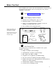
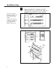
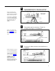
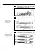
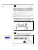
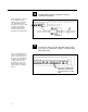
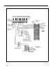
Table Of Contents
- Table of Contents
- General Information
- Before You Start
- Installation Steps
- Connecting Speakers
- Powering Up System
- Self-Powered Controller Connections
- Controller to Generic Amplifier
- Controller to Amplified Speakers
- Controller to PagePac 20
- Controller to AmpliCenter 100
- Controller to D-Series AmpliCenter
- Troubleshooting
- Controller Specifications
- Controls and Indicators, Terminals and Connector
- Connectivity Chart
- Programming the Controller
- General Zone and Zone Group Configurations
- Output Zone/Group Configurations
- Input Zone / Group Options
- Error Tones
- Programming Quick Reference Chart
- Zone Map and Zone Configuration Tables
- Application Notes
12
NOTE: For each zone used, no
matter what its function, this
switch needs to be set to one
of three settings for proper
zone operation.
CONTACT
CLOSURE OUTPUT
CONTACT
CLOSURE INPUT
70V AUDIO OUTPUT
SHIELDED FOR
TALKBACK
CONTACT
CLOSURE OUTPUT
CONTACT
CLOSURE INPUT
70V AUDIO OUTPUT
MOMENTARY
CONTACT CLOSURE
CONTACT
CLOSURE OUTPUT
CONTACT
CLOSURE INPUT
70V AUDIO OUTPUT
MOMENTARY OFF
MOMENTARY ON
RELAY POWER
The Controller has eight
switches for zones 1-8. Each
subsequent Zone Expansion
Unit has switches for zones
9-24, 25-40, and 41-56.
Refer to the Zone Map and
Zone Configuration Tables
filled out during facility paging
system design. You can find
these in the programming
section on page 29.
Set the Zone Option switches on the Controller and
Zone Expansion Units, if any.
SPEAKER SETTING
SIGNAL-IN SETTING
CONTACT CLOSURE SETTING
ZONE OPTION SWITCHES
CONTROLLER
ZONE EXPANSION UNIT
Figure 14. Setting Zone Option Switches on Controller and Zone Expansion
Units
Connecting Speakers
Locate and mount all speakers in accordance with the
floor plan drawing for this installation.
NOTE: Adjust all speakers per
volume and power
requirements as noted on floor
plan, during or after installation.
1
2
Figures 16 and 17, on the
following pages, show wiring
methods using local and zone
connector blocks, and contact
closure zone applications.
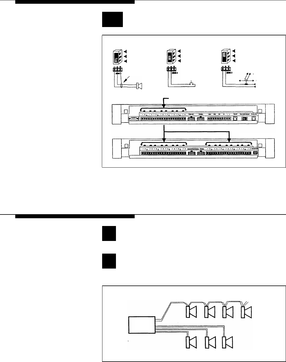
Connect each speaker to the appropriate Home Run
or Speaker-to-speaker wiring scheme as shown on the
floor plan.
SPEAKER-TO-SPEAKER METHOD
70 VOLT
AUDIO
OUTPUT
HOME RUN METHOD
Figure 15. Speaker Wiring Methods
9