
Specifications
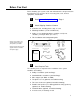
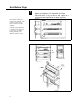
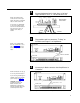
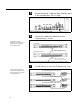
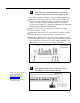
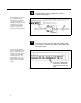
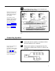
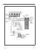
Table Of Contents
- Table of Contents
- General Information
- Before You Start
- Installation Steps
- Connecting Speakers
- Powering Up System
- Self-Powered Controller Connections
- Controller to Generic Amplifier
- Controller to Amplified Speakers
- Controller to PagePac 20
- Controller to AmpliCenter 100
- Controller to D-Series AmpliCenter
- Troubleshooting
- Controller Specifications
- Controls and Indicators, Terminals and Connector
- Connectivity Chart
- Programming the Controller
- General Zone and Zone Group Configurations
- Output Zone/Group Configurations
- Input Zone / Group Options
- Error Tones
- Programming Quick Reference Chart
- Zone Map and Zone Configuration Tables
- Application Notes
10
NOTE: Depending on the type
of host telephone system
interface port, the connection
may differ slightly from the
illustration to the right. A direct
4-conductor cord from the
Controller to the telephone
system can also be used,
bypassing the connector block.
11
NOTE: If the host telephone
system is an EKTS type, it will
provide a contact closure for
night bell. This night bell input
is wired to one of the eight
controller input zones, and
programmed as such. The
night bell ringing through the
paging system is an optional
feature.
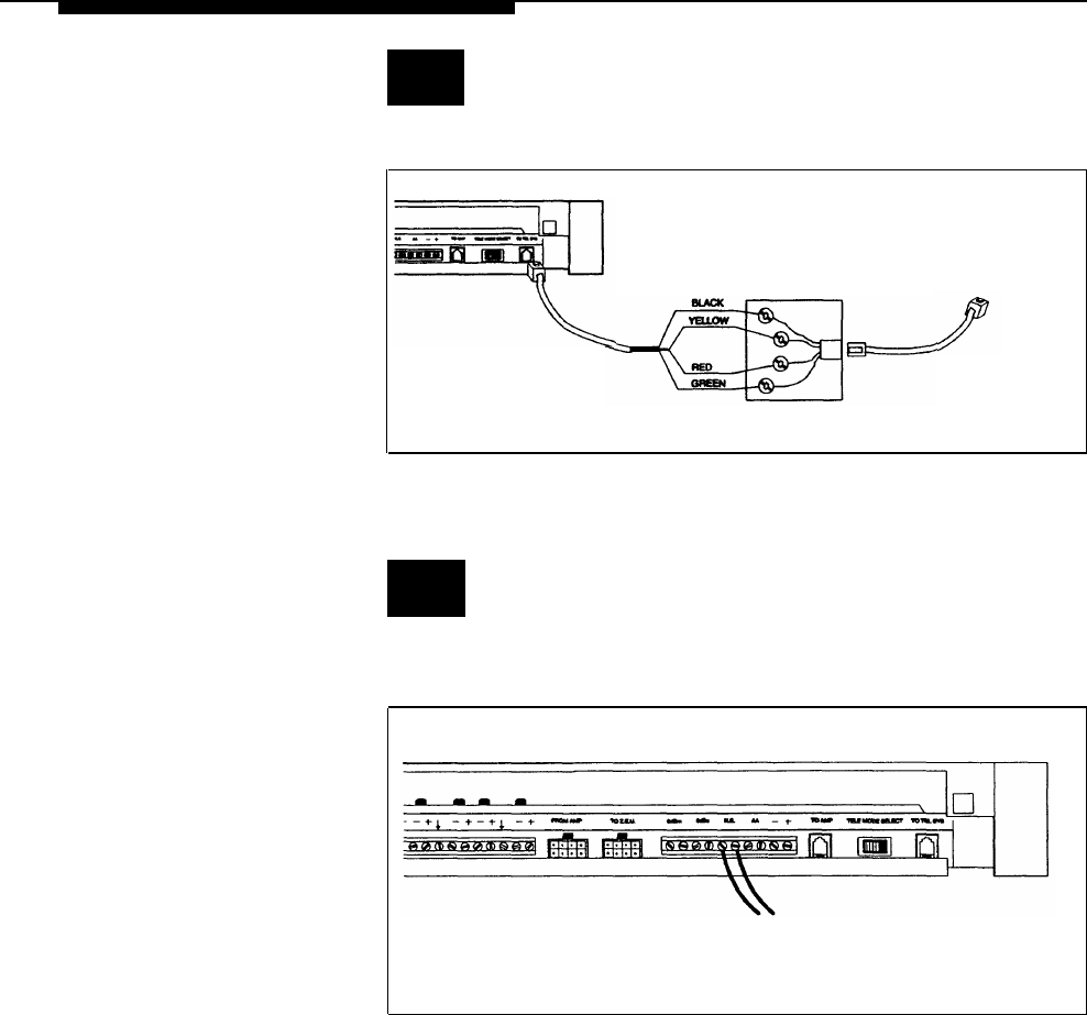
Controller Page Input.
Connect cable from host telephone system to
CONTROLLER
CONNECT BLACK WIRE TO THE PAIRED DRY CONTACT CONTROL LEAD GROUND
CONNECT YELLOW WIRE TO THE PAIRED DRY CONTACT CONTROL LEAD C1
CONNECT RED WIRE TO SYSTEM RING R
CONNECT GREEN WIRE TO SYSTEM TIP T
CONNECTION TO HOST
TELEPHONE SYSTEM
TO HOST TELEPHONE
SYSTEM INTERFACE
PORT
RJ-11 CONNECTOR
BLOCK
Figure 12. Connecting Host Telephone System to Controller
Connect two wires from the night bell analog station
port on the host telephone system to Controller night
bell (N.B.) input.
CONTROLLER
NIGHT BELL CONNECTION
FROM HOST TELEPHONE
SYSTEM ANALOG STATION
PORT
Figure 13. Night Bell Connection to Controller
8