
Specifications
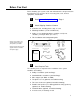
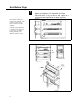
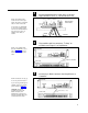
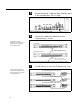
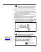
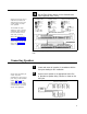
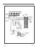
Table Of Contents
- Table of Contents
- General Information
- Before You Start
- Installation Steps
- Connecting Speakers
- Powering Up System
- Self-Powered Controller Connections
- Controller to Generic Amplifier
- Controller to Amplified Speakers
- Controller to PagePac 20
- Controller to AmpliCenter 100
- Controller to D-Series AmpliCenter
- Troubleshooting
- Controller Specifications
- Controls and Indicators, Terminals and Connector
- Connectivity Chart
- Programming the Controller
- General Zone and Zone Group Configurations
- Output Zone/Group Configurations
- Input Zone / Group Options
- Error Tones
- Programming Quick Reference Chart
- Zone Map and Zone Configuration Tables
- Application Notes
5
6
NOTE: Up to 3 Zone
Expansion Units can be used,
providing up to 56 paging
and/or control zones.
7
NOTE: These DIP switches
must be set correctly in order
for the Controller to recognize
the additional zones.
Set the AmpliCenter Telephone Mode Selection Switch
to Dry Loop 600 Ohms (Far left setting).
Figure 7. AmpliCenter Mode Switch Setting
Connect 8-pin Molex from Controller to Zone
Expansion Unit(s), if used.
CONTROLLER
POWER, CONTROL, 70V AUDIO
ZONE EXPANSION UNIT #1
POWER, CONTROL, 70V AUDIO
TO NEXT ZONE EXPANSION UNIT(S)
Figure 8. 8-pin Molex Connector from Controller to Zone Expansion Unit(s)
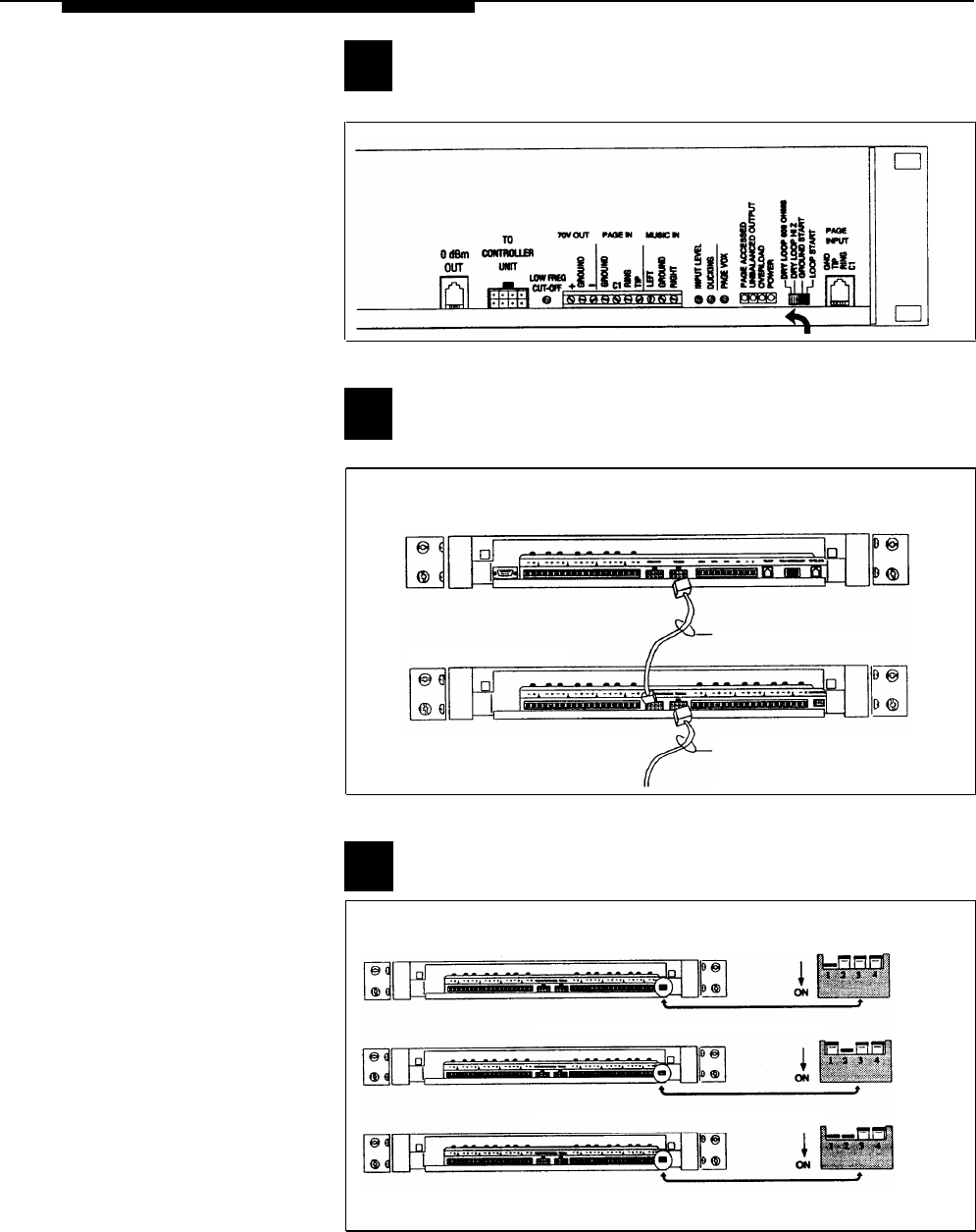
Set DIP switches on each Zone Expansion Unit, if any.
ON 1ST ZONE EXPANSION UNIT SET DIP SWITCH TO:
ON 2ND ZONE EXPANSION UNIT SET DIP SWITCH TO:
ON 3RD ZONE EXPANSION UNIT SET DIP SWITCH TO:
ENABLES
ZONES 9-24
ENABLES
ZONES 25-40
ENABLES
ZONES 41-56
Figure 9. Setting Zone Expansion Unit DIP Switches
6