
Specifications
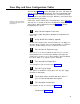
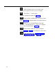
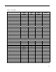
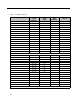
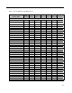
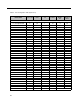
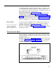
Table Of Contents
- Table of Contents
- General Information
- Before You Start
- Installation Steps
- Connecting Speakers
- Powering Up System
- Self-Powered Controller Connections
- Controller to Generic Amplifier
- Controller to Amplified Speakers
- Controller to PagePac 20
- Controller to AmpliCenter 100
- Controller to D-Series AmpliCenter
- Troubleshooting
- Controller Specifications
- Controls and Indicators, Terminals and Connector
- Connectivity Chart
- Programming the Controller
- General Zone and Zone Group Configurations
- Output Zone/Group Configurations
- Input Zone / Group Options
- Error Tones
- Programming Quick Reference Chart
- Zone Map and Zone Configuration Tables
- Application Notes
Zone Map and Zone Configuration Tables
The Zone Map (table 7) assists in identifying each zone, both input and
output, of your particular paging layout. The Zone Configuration table
(table 8) identifies each input and output zone, and their associated
features. Refer to your facilities floor plan. With these three tables filled
out, programming can begin.
NOTE: You may find it helpful
Follow steps 1 thru 3 and fill out the Zone Map tables on the next page,
to photocopy the tables and fill
and steps 4 to 11 and fill out the Zone Configuration (Output and Input
the copies out.
Zones) tables. When completed, proceed to page 29 and begin
programming the system.
Write a brief description of each zone.
For example, Lobby, Warehouse, Doorbell: Security Door, Fire
alarm, etc.
1
2
3
4
5
6
7
Assign ALlAS Zone Numbers (optional).
An Alias Zone Number if the extension number (3 or 4 digits) you
intend to dial to reach this zone. If an ALlAS number is assigned to
any zone, ALlAS numbers must be assigned to ALL zones.
Enter the Input or Output zone type.
Write an I-1, I-2, or an O to indicate the type of zone. I-1 means
input priority level 1; I-2 means input priority 2 (the higher the
priority zones get first access to the Controller). Input and Output
here mean inputs to, or outputs from, the Controller.
Fill in description of Output Zone.
See examples in step one. Refer to the Zone Map
Enter the Type of Output
The options are Audio/N.O., Mom. Open, N-C, Sys HS, Toggle,
Phantom, or AA Ready.
For the other features listed for that zone, enter a Y
(yes) or N (no) to implement those options.
Fill in description of Input Zone.
See examples in step one. Refer to the Zone Map
Continued on next page...
51