
Specifications
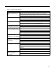
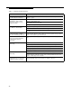
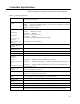
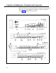
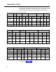
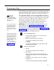
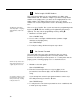
Table Of Contents
- Table of Contents
- General Information
- Before You Start
- Installation Steps
- Connecting Speakers
- Powering Up System
- Self-Powered Controller Connections
- Controller to Generic Amplifier
- Controller to Amplified Speakers
- Controller to PagePac 20
- Controller to AmpliCenter 100
- Controller to D-Series AmpliCenter
- Troubleshooting
- Controller Specifications
- Controls and Indicators, Terminals and Connector
- Connectivity Chart
- Programming the Controller
- General Zone and Zone Group Configurations
- Output Zone/Group Configurations
- Input Zone / Group Options
- Error Tones
- Programming Quick Reference Chart
- Zone Map and Zone Configuration Tables
- Application Notes
Connectivity Chart
The Controller Connectivity chart gives the interface requirements for the
host telephone systems listed. This information is then used to set the
telephone mode function switch on the PagePac Plus Controller.
Table 5. PagePac Plus Controller Connectivity Chart
System
Merlin Plus
Merlin 206/820
Merlin 1030/30/70 Merlin II Merlin Legend
2000
Set Mode
C.O. C.O. Page
C.O. Page
C.O.
Service
C.O.
Analog C.O. Analog
Switch To:
Line Line
Port
Line
Module
Line
Module
Line Station
Line
Station
Loop Start
Yes
Yes –
Yes –
Yes
–
Yes
–
Yes
–
Note 1
Note 1
Note 1
Note 1
Ground Start –
– –
–
–
–
–
–
–
–
–
Station Access
– – – – –
– –
–
Yes
– Yes
Note 2 Note 3
Dry Loop (600
Ω)Ω)
–
–
–
–
–
–
– –
–
–
–
Spirit 308/616
Spirit Partner Plus
Partner II
1224/2448
Set Mode
C.O. Line Page Port C.O. Line
C.O. Line
Analog Page Port
C.O. Line Analog
Page
Switch To:
Station
Station
Port
Loop Start
Yes
–
Yes
Yes
–
–
Yes
–
–
Ground
–
–
– –
–
–
–
–
–
Start
Station –
– – –
Yes
–
–
Yes
–
Access
Note 5,6
Note 4,6
Dry Loop
–
–
– –
–
Yes
–
–
Yes
(600
Ω)Ω)
Note 7 Note 7
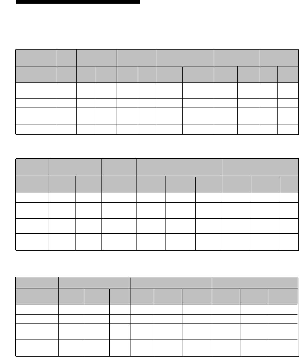
System 25
System 75/G1/G3I Definity
System 85/G2
Set Mode
C.O. Line
Analog Aux.
C.O.
Analog
Aux. Port
C.O. Line Analog
Aux. Port
Switch To:
Station
Port
Line
Station
Station
Loop Start
Yes
– –
Yes –
– – –
–
Ground Start
Yes – –
Yes –
–
Yes
–
–
Station Access
–
Yes – –
Yes
– –
Yes
–
Note 4
Note 4 Note 4
Dry Loop
– –
Yes –
Yes
–
Yes
(600
Ω)Ω)
Note 8 Note 8 Note 8
Continued on next page...
26