
Specifications
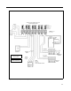
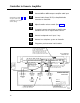
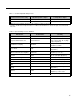
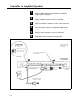
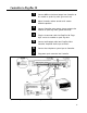
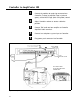
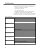
Table Of Contents
- Table of Contents
- General Information
- Before You Start
- Installation Steps
- Connecting Speakers
- Powering Up System
- Self-Powered Controller Connections
- Controller to Generic Amplifier
- Controller to Amplified Speakers
- Controller to PagePac 20
- Controller to AmpliCenter 100
- Controller to D-Series AmpliCenter
- Troubleshooting
- Controller Specifications
- Controls and Indicators, Terminals and Connector
- Connectivity Chart
- Programming the Controller
- General Zone and Zone Group Configurations
- Output Zone/Group Configurations
- Input Zone / Group Options
- Error Tones
- Programming Quick Reference Chart
- Zone Map and Zone Configuration Tables
- Application Notes
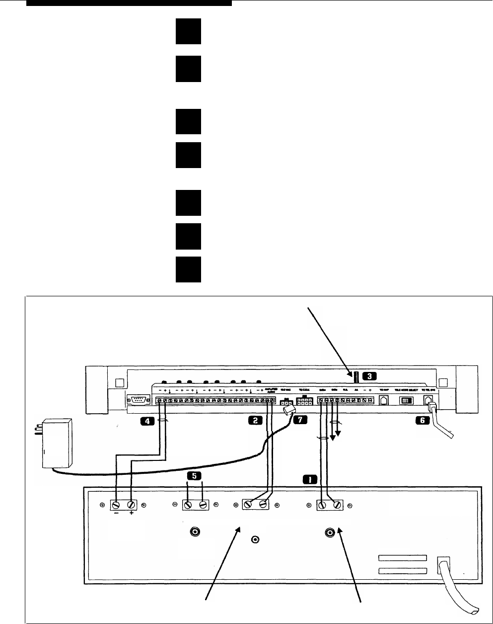
Controller to Generic Amplifier
1
2
3
4
5
6
7
NOTE: Refer to Tables 1 and 2
for proper audio input
requirements and volume
control settings.
Connect 0dBu or 0dBm output to amplifier audio input.
Connect Audio Output (70.7V) to Amplified Audio
connector on Controller.
Adjust Controller volume control (See table 1)
If required, connect control input to amplifier from
Controller zone set to “output contact closure.”
Connect background music input, if any.
Connect host telephone system to Controller.
Plug power pack connector into Controller.
ADJUST OUTPUT VOLUME CONTROL
TO MATCH THE INPUT SENSITIVITY
OF THE GENERIC AMPLIFIER.
REFER TO "INPUT SENSITIVITY" TABLE
FOR THE AMPLIFIER, THEN FIND THE
PROPER VOLUME CONTROL SETTING
IN THE "ADJUSTABLE GAIN LEVELS" TABLE
SELF-POWERED
CONTROLLER
THIS CONNECTION
LOW (0 dBu)
REQUIRED ON SOME
AMPLIFIERS TO ENABLE
OUTPUT IMPEDANCE
600 OHM
16.5 VAC THE PAGE MODE. SET
(0 dBm)
POWER
ZONE 1 SWITCH FOR
OUTPUT
USE EITHER THE 600 OHM or LOW OUTPUT.
MODULE
OUTPUT CONTACT CLOSURE
IMPEDANCE
SEE "ADUSTABLE GAIN LEVELS" TABLE
FOR OUTPUT RANGE SETTING
TO HOST
TELEPHONE
SYSTEM
GENERIC AMPLIFIER
REAR PANEL
PAGE/MUSIC
CONTROL
INPUT
MUSIC IN
AUDIO OUTPUT
70.7V
AUDIO INPUT
RADIO
CD OR TAPE
PLAYER
MODEL No.
SERIAL No.
AMPLIFIED AUDIO OUTPUT
TELEPHONE INPUT
CAN BE, BUT NOT LIMITED TO:
MICROPHONE INPUT
100, 70.7, 25, and 3.5 Vrms
or 16, 8, and 4 OHM or LOW LEVEL
(DRY INPUT, NO BATTERY
OR VOLTAGE CAN BE PRESENT)
Figure 18. Connection of the Self-powered Controller to Generic Amplifiers
14