
Specifications
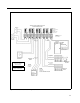
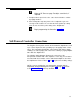
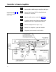
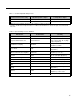
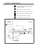
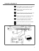
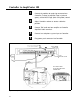
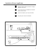
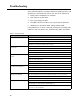
Table Of Contents
- Table of Contents
- General Information
- Before You Start
- Installation Steps
- Connecting Speakers
- Powering Up System
- Self-Powered Controller Connections
- Controller to Generic Amplifier
- Controller to Amplified Speakers
- Controller to PagePac 20
- Controller to AmpliCenter 100
- Controller to D-Series AmpliCenter
- Troubleshooting
- Controller Specifications
- Controls and Indicators, Terminals and Connector
- Connectivity Chart
- Programming the Controller
- General Zone and Zone Group Configurations
- Output Zone/Group Configurations
- Input Zone / Group Options
- Error Tones
- Programming Quick Reference Chart
- Zone Map and Zone Configuration Tables
- Application Notes

3
Test speaker wiring for short circuits
Measure the resistance of each home run wiring with an ohmmeter.
Any pair indicating a value of less than 15 ohms must be rechecked
for possible shorted wiring or speakers. Correct any problems and
retest.
4
Make zone connections to Controller and any Zone
Expansion Units. (See Figure 16)
The zone connectors on the Controller and Zone Expansion Units can
accommodate up to two 22 AWG wires or four 24 AWG wires per zone
output.
NOTE: DO NOT over tighten
Check zone option switch setting with Zone Map and Zone Configuration
zone connector screws.
Tables as you connect each zone (A 70V audio output setting going to
other than speakers may damage other equipment).
Powering Up System
With all zones wired and connected to the Controller and Zone
Expansion Units (if any), initial testing can begin. Refer to Figure 24,
Controls and Indicators. Once initial testing is done, you can begin to
program the Controller with the features for each zone.
NOTE: If during power up, the
system does not respond as
described, refer to the
Troubleshooting section
1
1.
2.
3.
If an amplifier other than the
AmpliCenter is used, make
sure it is powered up and
verify the Controller LEDs.
4.
5.
Plug the power cord into the A.C. input connector on
the AmpliCenter. The following should happen.
The green Power LED on the AmpliCenter will turn on and stay on.
The green Page Access LED on the AmpliCenter also turns on, but
will go out after a few seconds.
On the Controller, verify that the green Phone System Enabled LED
if off.
On the Controller, verify that the yellow Attendant Access Enabled
LED is off.
If background music is connected, adjust the Music In Input Level
control on the AmpliCenter(s) for an acceptable level.
Continued on next page...
12