
Specifications


Module Components
The PARTNER PagePac unit can be mounted directly to a wall or on a
desk next to your current PARTNER Plus or PARTNER II phone system
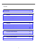
installation (see Section 2, Installation for complete information). The
information key in Figure 1-1 below illustrates the location and description
of the PARTNER PagePac features.
PARTNER PagePac
Module
STATION INTERFACE RJ-11 JACK
This jack is the PARTNER PagePac
interface to your PARTNER Plus or
PARTNER II phone system. Any one
of three connection modes ensure
the best possible compatibility to
your current phone system.
NIGHT BELL SERVICE
Through this RJ-11 jack and your
current PARTNER phone system,
night bell service is integrated into the
PARTNER PagePac paging system.
MICROPHONE INPUT
Connect a high-fidelity microphone
to this RJ-11 jack for simple
attendant paging access.
POWER ON LED
AUXILIARY AMPLIFIER (ZONE 3)
This RJ-11 jack provides a
0 dB page/music output
along with a contact
closure pair for connection
to a customer provided
auxiliary amplifier.
MUSIC INPUT
This RCA jack can be used
to connect a customer
provided music source.
Zone 1 and Zone 2
These two RJ-45 jacks can be
individually configured for page/
speaker zones, auxiliary amp zones,
or doorspeaker zones - providing
an audio pari as well as three
contact closure pairs.
ERROR LEDs
Error LEDs are provided to signal
If paging zone draws too much
current (1.2 Amps max.) per zone.
Figure 1-1. PARTNER PagePac Paging System Features (Inputs / Outputs)
Overview 1-3