
Installation guide

Connectors on Rear
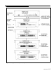
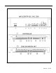
You have access to controls and connections on the back panel, which is
covered with a removable lid (see figure 1-2). For instructions on installing
the PagePac Plus system and making correct interconnects, see the
Installation Guide.
■
■
■
■
■
■
■
■
The rear panel of the PagePac Plus Control Unit contains:
Two RJ11 telephone-type jacks, one for your PBX telephone system to
connect to the PagePac Plus (Telephone Access) and one for the
interconnect from the PagePac Plus to the PagePac Plus Amplicenter.
A telephone interface mode selection switch (set during installation) to
match your telephone system.
A connector for the RS-232 port, which is used to connect a PC
computer.
A 10 position connector for Attendant Access inputs (from microphone
or master telephone console), the Night Bell ringer input, and two audio
outputs.
A 20 position connector for zone connections and shields.
Two 8-position connectors, one for the interconnect to the PagePac
Plus Amplicenter, which supplies power and 70V audio to the
controller, and one for an interconnect to Zone Expansion Units (if
used).
Eight 3-position zone switches, to manually configure a zone to be
contact closure (switch), input, or audio output.
Power
Two DC voltages derived from the PagePac Plus Amplicenter (D-20,
D-100, or D-300) via the interconnect cable are the source for all power
required by the PagePac Plus Control Unit and any attached Zone
Expansion Units.
See discussion of the front panel Power On LED, above under "LED
Indicators."
1-14 Overview