
Installation guide

Whether the PagePac Plus system is configured as a constant-voltage
distribution system, a controller system, or as a hybrid system, has no
bearing on programming and using the system.
For full information about connecting hardware, see the Installation Guide.
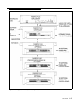
Constant-Voltage
This is the "traditional" paging system configuration. When the system is
Distribution System
configured as a constant-voltage distribution system, the 70V Amplicenter
audio output is routed via the controller to any zone that is optioned for
audio.
Controller System In this configuration, the required PagePac Plus Amplicenter’s audio will
only be sent to a specific selected zone. Both remote audio amplifiers and
amplified speakers can be controlled in this mode as well as other
ancillary equipment requiring an audio output or a contact closure, or both.
Hybrid System In this configuration the features of the constant-voltage distribution system
and the features of the controller system will be combined. The controller
will route the 70V audio to the proper audio zone and also have the ability
to control remote amplifiers with zones selected as control closures.
Indicators and Connectors
LED Indicators
Front panel
Rear panel
The PagePac Plus Controller has three LED indicators that are useful for
installation and troubleshooting purposes.
A single LED indicates the unit’s power status: solid green indicates the
unit has power, and blinking green indicates that the unit is in reset mode.
A blinking power LED may indicate the need to power down and power up
again, or that there is not enough AC power to the Amplicenter or DC
power from the Amplicenter to the controller.
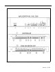
Two LEDs are adjacent to the eight zone option switches (see figure 1-2).
The green LED lights to indicate that the Telephone Access interface has
successfully been accessed by the telephone equipment. The yellow LED
lights to indicate that Attendant Access interface has been successfully
accessed.
Back Panel Nomenclature
The following items describe all back panel functions illustrated in figure 1-2:
Overview 1-11