
Specifications


Controls and Indicators, Terminals and Connectors
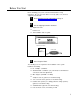
Figure 10 shows the controls and indicators, terminals and connectors on
the rear panel of the AmpliCenter. Table 2 identifies them by function.
AMPLICENTER
Figure 10. AmpliCenter Controls and Indicators, Terminals and Connectors
Table 2. Controls and Indicators, Terminals and Connectors
1.
AC Power in: 105 – 125 VAC, 210-250 VAC, 50/60 Hz, (voltage auto-selectable within unit)
2.
0dBm out, an auxiliary output that differs from the main 70.7V output in that it is a low level (0dB), 600
ohm balanced output used for driving a remote or off-premises amplifier
3.
DC Power, and 70V audio out to Controller (used only if Controller is also installed)
4.
Bass control screw-type adjustment pot. Attenuates low frequencies so that horns and small speakers
are not overdriven by excessive bass energy. Cut off frequency is adjustable from 50 Hz (full CCW) to
400 Hz (full CW)
5.
Music In: left and/or right channels with ground;
Paging In: redundant paging input (ground, C1, tip, and ring)
70V Out: Balanced output used for terminating the loudspeaker wiring
6.
Screw adjustable potentiometers: VOX sensitivity level, Music ducking (mute level for music during voice
page), Music level for various music sources
LEDs: green – power on, lights when AC line voltage is applied to AmpliCenter.
7.
red – overload, lights when the AmpliCenter output exceeds its output power rating.
This can occur when total speaker load is greater than the output rating, or
when speaker wiring is shorted.
red – unbalanced output, indicates when one speaker lead is accidentally shorted to ground.
green – page accessed, lights when voice paging is active.
8.
Telephone system mode switch: dry loop 600 ohms, dry loop Hi Z, ground start, or loop start
9.
Page input from host telephone system or Controller RJ11 connector: paging audio and control
9