
Installation guide
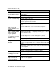

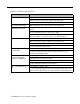


Index
A
AC power
Addresses
Zones
Amplicenter
Approvals
AT&T customer information center
Attendant console
Audio paging zones
Auxiliary equipment
B
Back panels
Bass
C
Circuit protection
Comment on this guide
Communication system interface
Computer monitor logging
Connections
Contact closure
Paging zones
Connectivity chart
Connector
Host system
Connectors
Contact closure input zones
Testing
Contact closure output zones
Testing
Contact closure zone connections
Contact closure zone wiring
Diagram
Controller
Wiring to zones
Zone wiring diagram
Controller system
2-4, 3-21
3-16
1-10
2-3
1-8
3-16
3-21
2-6
2-5
2-4
2-2
1-8
3-18
3-18
3-13
3-11
1-6
3-19
2-3 — 2-4
3-23
3-22
3-13
3-14
1-10
3-12
3-14
3-4
Controller system setup
Diagram
Controls
Customer helpline
Customer support
D
DIP switch
Dry loop
E
Example system setup
F
FCC
Interference Notice
Registration part 15
Statement part 68
Statement/registration
Features and capabilities
Feedback form
G
Ground start
H
Hardware
Installation diagram
Installation steps
Mounting
Mounting, wall diagram
Rack mounted, diagram
Hardware
Hardware configuration
Host systems
Hybrid system
3-6
2-3, 2-4
ii
1-3
3-15
3-19
3-4
2-3
ii
A-2
A-1
A-1 — A-4
1-10
B-1, 1-8
3-19
1-5
1-4
3-8
3-9
3-10
3-1 — 3-23
1-3, 2-1 — 2-6
1-6
3-4
Index IN-1