
Installation guide


Connectivity Chart
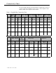
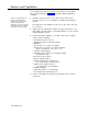
The Connectivity chart gives the trunk interface requirements for the host
systems listed. This information is then used to set the telephone mode
function switch on the PagePac Plus Controller.
Table 1-1. PagePac Plus Connectivity Chart
System
2000
Merlin Plus
Merlin 206/820
Merlin 1030/3070
Merlin II
Merlin Legend
Mode
C.O.
Line
C.O.
Line
Page
Port
C.O.
Line
Page
Module
C.O.
Line
Service
Module
C.O.
Line
Analog
Station
C.O.
Line
Analog
Station
Loop
Start
Ground
Start
Dry
Loop
(Hi Z)
Dry
Loop
(600Ω)
Yes
Yes
Note 1
—
—
— —
——— ——
———
—
No
Yes
—
Yes
Note 1 Note 1
— — —
—
No
—
——
Spirit 308/616
Spirit
1224/2448
Partner Plus
Partner II
Mode
C.O.
Line
Page
Port
C.O. Line C.O. Line
Analog
Station
Page
Port
C.O.
Line
Analog
Station
Page
Port
Loop
Yes
—
Yes
Start
Ground
— — —
Start
Dry
— —
Loop
(Hi Z)
——
—
Dry
—
No
—
Loop
No
Yes
—
— —
—
—
Yes
—
Yes
—
Note 1
—
— — —
—
— —
—
—
— — —
—
Yes
— —
— —
—
—
— —
— —
Yes
—
— Yes
Note 2
Note 2
1-6 Overview