AT&T ® PARTNER Plus Communications System Release 4.
Copyright © 1994 AT&T All Rights Reserved Printed in U.S.A. AT&T 518-455-222 Issue 1 August 1994 Notice Every effort was made to ensure that the information in this book was complete and accurate at the time of printing. However, information is subject to change. Federal Communications Commission (FCC) Interference Notice This equipment has been tested and found to comply with the limits of a Class A digital device, pursuant to Part 15 of FCC rules.
Contents Contents Important Safety Instructions ii Overview 1 An Example System Setup 2 Required Parts 4 Installation Guidelines 5 ■ ■ Telephones and Devices Combination Extensions Using A Direct Connection Using a Bridging Adapter Installation Procedures ■ ■ ■ ■ ■ ■ ■ Installing the Control Unit and Modules Connecting Lines and Extensions Connecting Caller ID Display Units Assembling System Phones Desk Mounting Wall Mounting Connecting and Testing Telephones Connecting Paging, Music-On-Hold
Important Safety Instructions The following list provides basic safety precautions that should always be followed when using your telephone equipment: 1. Read and understand all instructions. 2. Follow all warnings and instructions marked on the product. 3. Unplug all telephone connections before cleaning. DO NOT use liquid cleaners or aerosol cleaners. Use a damp cloth for cleaning. 4. This product should be serviced by (or taken to) a qualified repair center when service or repair work is required.
Installation Overview This guide explains how to install the PARTNER® Plus Communications System. It begins with an example system setup, then follows with an illustration of the components you need to install the system and general guidelines to consider before installation. Next, it provides step-by-step instructions for connecting and testing the components for initial installation and upgrades. Finally, it ends with important system specifications and requirements.
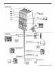
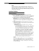
An Example System Setup The next page shows a control unit with two 206 modules and two 400 modules, giving the system a capacity of 12 outside lines and 12 extensions. Although your system may differ, this example will give you an idea of the types of equipment you can connect to it. In the example, system phones and industry-standard devices are connected to nine extensions. The circled numbers in the figure refer to the following list, which gives a brief description of the system’s hardware components.
An Example System Setup 3
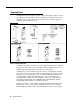
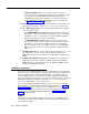
Required Parts You will have up to three types of system component packages; Figure 1 shows the contents of each package in the area marked by a dashed line. Check your packages to be sure you have the parts shown here (if not, call for support as instructed on the inside front cover). Figure 1. Required Parts You will need to obtain four #12 screws of the appropriate type for the wall and weight of the control unit (a control unit with four 206 modules and a processor module weighs approximately 27.
NOTE: A system display phone—either an MLS-34D, MLS-18D, or MLS-12D—is required for system programming at extension 10 and/or 11. (Make sure that the programming phone is as large as the largest phone in the system, because an MLS-12D or MLS-18D cannot program an MLS-34D. Similarly, an MLS-12D cannot program an MLS-18D.) Installation Guidelines Telephones and Devices You can connect the following telephones and devices to the system: ■ MLS- and MLC-Model System Phones.
– Auxiliary Equipment. There are a variety of ways to set up fax machines, modems, and answering machines to work with the system. See Chapter 4 in the PARTNER Plus Communications System Programming and Use guide for advice on using this equipment. To connect a telephone and a standard device on the same extension, see “Combination Extensions” on page 6. ■ Doorphones. You can connect up to two doorphones to the system. Do not connect doorphones to extension 10, 11, 16, 17, 22, 23, 28, or 29.
Using A Direct Connection Figure 2 shows how to connect a standard device directly to a system phone, using the phone’s built-in auxiliary jack. Figure 2. Combination Extension Using Direct Connection Using a Bridging Adapter Figure 3 shows how to connect a system phone and a standard device or two standard devices together using the 267F2 bridging adapter. Figure 3.
Installation Procedures Before installing the system, be sure you read the safety instructions on page ii. WARNING: There are no customer-serviceable components inside the system modules or backplane. There are hazardous voltages within that can cause severe or fatal personal injury. DO NOT OPEN THE MODULES. Installing the Control Unit and Modules Install the control unit’s backplane within five feet (1.
4 5 A) To power down the control unit, pull out the main circuit breaker on the control unit or move the on/off switch to the “off” position (“O”), depending upon which hardware configuration you have. B) Press the AC power cord firmly into the power jack on the top right side of the backplane until it locks into place. C) Plug the other end of the power cord into a properly grounded three-prong wall outlet not controlled by a switch.
Connecting Lines and Extensions If extensions are not wired to any modular jacks, call a qualified service technician. 1 A ) Test for dial tone at the network interface jacks before connecting outside lines to the control unit. For the test, connect a standard phone to the first network interface jack. B ) Lift the handset and listen for dial tone. (If there is no dial tone, contact your local telephone company before continuing.) 2 3 4 10 C) Repeat for each network interface jack.
5 A ) Connect modular telephone cords to 206 module extension jacks, starting at the top extension jack on the leftmost module. B ) Route each cord through the hook on the front of the module, and then push the cords through the space below the module and out through the back. C ) Pull the cords from behind the backplane, leaving at least two feet (0.6 meters) of slack to allow easy replacement of system modules (for future maintenance so you can easily reconnect cords after replacing system modules).
Connecting Caller ID Display Units To get Caller ID information for an extension, you must first subscribe to the service (on a per-line basis) from your local telephone company, then connect the units as described here. You must connect the Caller ID display unit directly to the line that supports Caller ID at the network interface jack. Additionally, you must provide a separate wiring run for the unit to the appropriate location.
Assembling System Phones You can either desk mount or wall mount a system phone. If the system phone is manufactured with a separate stand, you can use the stand to either wall mount the phone or raise the angle of the phone when desk mounting. (The stand is required for MLS-34D phones.) Alternatively, some system phones—such as the MLS-18D—are manufactured with a fixed stand. Any instructions below for installing the stand do not apply to this type of phone.
Wall Mounting If you wall mount a display phone, the display may be difficult to read, so desk mounting is recommended. (Wall mounting instructions apply to corded MLS-model phones only. To wall mount an MLC-6 cordless phone, follow the instructions in the booklet provided with the phone.) Wall Mounting Phones with Separate Stands 1 2 3 Reverse the plastic hook that sits in the earpiece part of the handset cradle.
2 A ) Unscrew the phone’s four mounting screws and lift the base of the phone off the top. CAUTION: Do not touch electrical circuitry. To do so will expose you to a risk of electrical shock and possibly damage the equipment. B ) Turn the base of the phone upside down so that the phone base can be mounted parallel to the wall—and then place it back on the base. C ) Replace the four mounting screws.
Connecting Paging, Music-On-Hold, and Call Reporting (SMDR) Devices Only steps for connection to the processor module are provided here. Refer to the manufacturer’s instructions for additional information on installing and using these devices. Paging System 1 2 Insert the modular plug into the PAGE jack on the processor module. Route the cord as you did for line and extension cords, then connect it to the paging system.
Connecting Intercom Autodialers Since the autodialer has a fixed stand, you may need to adjust the height of the system phone—by installing a stand—to match the height of the autodialer. Refer to Step 2 of “Desk Mounting” under “Assembling System Phones” for instructions. You can wall mount an Intercom Autodialer to work next to a wall-mounted system phone; however, wall-mounting system display phones is not recommended.
Equipment Upgrades Adding New Modules 1 A ) To power down the control unit, pull out the main circuit breaker or move the on/off switch to the “off” position (“O”), depending upon which hardware configuration you have. B ) To remove the cover, place one hand on the handle on the bottom front of the cover and place your other hand on the top of the cover. C ) Gently pull the cover up from the bottom and tilt it towards the top until it detaches from the backplane.
5 A) To replace the cover, while holding the cover at an angle, gently move the top rear edge of the cover over the top of the control unit and match up the grooves where the top edge of the cover meets the backplane. Gently push the edge into place. B) Lower the bottom of the cover until it is secured in place.
3 4 A) Connect the line and extension cords one at a time, making sure to place the correct cords into their corresponding jacks on the new module. B) To power up the control unit, push in the main circuit breaker, or move the on/off switch to the “on” position (“I”). Check all green lights on the fronts of the modules. If all the lights are lit, installation is complete; otherwise: A) If a single light is out, power down the control unit, reseat the module, then power up the control unit.
Specifications Capacities ■ ■ ■ ■ ■ ■ Dimensions and Weights (approx.
Electrical Specifications ■ ■ ■ ■ ■ Processor Module Specifications Extension Jack Specifications ■ 68000 microprocessor, 128Kbytes RAM, 512Kbytes ROM ■ Ringing voltage: +5VDC, -140 VDC peak to peak; trapezoidal wave shaping 35- to 38-Volt talk battery Ringing frequency: 20 Hz ■ ■ PAGE Jack Specifications ■ ■ ■ SMDR Output Format ■ ■ ■ ■ ■ ■ ■ Environmental Requirements— Control Unit ■ ■ ■ ■ ■ ■ Electrical Requirements 22 Specifications 10 Watts (35 BTUs/hour) per 400 module, normal an
Requirements for Out-of-Building Extensions ■ ■ ■ Wiring ■ ■ ■ ■ Safety Requirements ■ ■ ■ Government Approvals and Local Phone Company Information Installation of a telephone or other standard (tip/ring) device in another building requires the following In-Range Out-of-Building (IROB) protectors to protect the control unit and device from electrical surges: System phone: two AT&T IROB protectors Standard device: one AT&T IROB protector plus one carbon block protector System phones: AT&T SYSTIMA
518-455-222 Issue 1 August 1994 Graphics © AT&T 1988