AT&T ® PARTNER Communications System Release 4.
Copyright © 1994 AT&T All Rights Reserved Printed in U.S.A. AT&T 518-455-113 Issue 1 November 1994 Notice Every effort was made to ensure that the information in this book was complete and accurate at the time of printing. However, information is subject to change. Federal Communications Commission (FCC) Interference Notice For important FCC interference, registration, and repair information, see Appendix E of this book.
Contents 1 About This Guide iii Overview 1-i 1-ii ■ ■ ■ ■ 2 Customizing Your System ■ ■ ■ ■ 3 1-1 1-2 1-3 2-i 2-1 2-2 2-2 2-3 3-i 3-1 ■ System Telephones Standard Telephones ■ Combination Extensions 3-10 Using Auxiliary Equipment ■ ■ ■ ■ ■ 5 System Options Telephone Options Changing Option Settings PBX or Centrex Services Support Learning About Telephones ■ 4 Important Safety Instructions Features and Capabilities System Components Auxiliary Equipment Overview Answering Machines Cred
Contents 6 Troubleshooting ■ ■ ■ When You Need Help Power Failure Operation Problems and Solutions 6-i 6-1 6-1 6-2 A User Form A-1 B Specifications B-1 C Installation C-1 D Maintenance, Repair, and Ordering Information D-1 E FCC Information E-1 GL Glossary GL-1 IN Index IN-1 Customization Quick Reference Inside back cover ii
About This Guide Purpose This guide explains how to set up and use the PARTNER® Communications System. It is intended for the person who will install and manage the system. Terminology Throughout this guide, the PARTNER Communications System is referred to simply as the system and AT&T telephones specifically designed to work with the system are called system phones. You can also use industry-standard telephones with the system, which are referred to as standard phones in this guide.
■ Solving Problems. Chapter 6 provides information on solving problems if your system or telephones malfunction. Once you are experienced with the system, use the Table of Contents or Index to locate the information you need. Throughout this guide, feature names are printed in bold so you can easily look up the name in Chapter 5, “Feature Reference,” for additional information on the feature. For example, if you see a reference to System Date (#101), you can look it up in Chapter 5 for details.
How to Comment on This Guide A feedback form is located at the end of this guide, after the appendixes. If the feedback form is missing, send your comments and recommendations for changes to Publications Manager, AT&T, 211 Mount Airy Road (Room 2W-226), Basking Ridge, NJ 07920 (FAX 1 908 953-6912).
Overview 1 Contents Features and Capabilities System Components ■ ■ System Modules System Phones Auxiliary Equipment ■ Combination Extensions 1-1 1-2 1-2 1-3 1-3 1-5 1-i
Important Safety Instructions WARNING: The following list provides basic safety precautions that should always be followed when using your telephone equipment: 1 . Read and understand all instructions. 2 . Follow all warnings and instructions marked on the product. 3 . Unplug all telephone connections before cleaning. DO NOT use liquid cleaners or aerosol cleaners. Use a damp cloth for cleaning. 4 .
Overview 1 Features and Capabilities Your system is easy to install, set up, and use. It can handle up to four outside telephone lines and up to 12 extensions. In addition, the system offers many features that help you manage phone calling: ■ Full line of system phones, some with displays showing date, time, and other messages; all with access to multiple telephone lines. ■ Easy operation of basic call handling capabilities including transfer, conference, and hold.
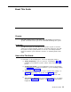
System Components Interchangeable parts make it easy to install or expand the system. Figure 1-1 shows an example of system components. A brief description of each component follows. SYSTEM MODULES SYSTEM PHONES 206 Module 200 Module Module Connector MLS-18D® Phone MLS-12® Phone Outside Line Jacks Power Indicators (LEDs) Extension Jacks (206 modules only) MLS-6® Phone MDC 9000 Phone MDW 9000 Phone Figure 1-1. Sample System Components System Modules ■ 206 Module.
■ Module Connector. This connector is needed only if you have two modules. It joins the modules together so that all the lines and extensions are connected. System Phones This guide refers to AT&T telephones specifically designed to work with the system as system phones. These include the MLS-18D, MLS-12D, MLS-12, MLS-6, MLC-6, MDC 9000, and MDW 9000 telephones.
■ Music-on-Hold systems allow you to play recorded music to callers while they are on hold. (Alternatively, the system supports a Tones on Hold feature. For more information, see “Music/Tones On Hold ” in Chapter 5.) ■ Extra alerts are strobes, lights, chimes, horns, or bells that light or ring when calls come in. They can connect to either en extension jack or a line jack. AT&T offers several compatible alerts.
Combination Extensions You can connect a standard device on an extension by itself, or have it share an extension with another piece of equipment. An extension with two devices connected to it is called a combination extension.
Customizing Your System 2 Contents System Options 2-1 Telephone Options 2-2 Changing Option Settings 2-2 PBX or Centrex Services Support 2-3 2-i
Customizing Your System 2 After installation is completed, your system is operational and ready to use. However, you may want to customize it to meet the requirements of your business. When the system is first installed, it uses factory settings that reflect the most common usage. However, you can change the option settings. There are two types of options: system options and telephone options. Both are discussed in this chapter.
Telephone Options Telephone options let you further customize individual extensions in the system. For example, you can specify which outside lines ring at an extension and you can store phone numbers on programmable buttons on system phones. Telephone options to consider are: ■ Automatic Line Selection allows you to select the sequence of lines through which the system searches to find a free line when the user makes a call.
Keep in mind the following general guidelines when changing option settings. Detailed procedures for changing each option are provided in Chapter 5. ■ To change settings, you press [ Feature ] [ 0 ] [ 0 ] at extension 10. At this point, the phone beeps and the light next to [ Spkr ] is green flutter. Then press left [ Intercom ] twice. The light next to left [ Intercom ] is green steady. ■ Some options are identified by # and a three-digit code (for example, System Date is #101).
Learning About Telephones 3 Contents System Telephones ■ ■ ■ ■ ■ Buttons and Indicators Lights Ringing Patterns Dial Tones Using the Speaker and Microphone Hands-Free Answer on Intercom (HFAI) Speakerphone Performance Tips Standard Telephones ■ ■ ■ ■ ■ Ringing Patterns Dial Tones Using the Switchhook Limitations Feature Phones Combination Extensions 3-1 3-2 3-4 3-5 3-5 3-5 3-6 3-7 3-7 3-8 3-8 3-8 3-9 3-9 3-10 3-i
Learning About Telephones 3 This chapter explains how system and standard phones work with the system, as well as combination extensions where more than one phone or auxiliary device is installed. System phones are described first, followed by standard phones on page 3-7 and combination extensions on 3-10. System Telephones System phones have some buttons and indicators in common. The following pages explain where they are and how they work.
Buttons and Indicators MLS-18D Display Programmable Auto Dial Buttons (8) Calling Feature Buttons (4) Line Buttons (4) Intercom Buttons (2) Display MLS-12D Programmable Auto Dial Buttons (8) Calling Feature Buttons (4) Line Buttons (4) MLS-12 Intercom Buttons (2) The following buttons and displays appear on system phones: Display.
MLS-6 Line Buttons (4) Intercom Buttons (2) Earpiece Volume Control Switch (MLC-6 and MDC 9000) or Volume Control (MDW 9000) MLC-6/ MDC 9000/ MDW 9000 (Handset) Line Buttons (4) Handset Display Intercom Buttons (2) MLC-6 and MDC 9000: MDW 9000: MLC-6/MDC 9000 (Base) MDW 9000 (Base) Mic (MLS-18D, MLS-12D, and MLS-12 only). Press to turn the microphone on and off. The light next to this button shows when the microphone is turned on. Leave on to use Hands-Free Answer on Intercom (HFAI) feature.
Lights Each line button, each calling feature button, and some Auto Dial buttons have a green light and a red light. The meaning of these lights varies, depending on whether a button is used to access an outside line, a calling feature, or an intercom Auto Dial number. Table 3-1 shows the meanings of the various light patterns for each possible button assignment. Table 3-1.
Ringing Patterns You can tell what kind of call you are receiving by the way your system phone rings: ■ An outside call will ring . . . ring . . . ring. ■ An intercom call will ring BEEP . . .ring BEEP . . . ring BEEP. If you have a system display phone, the caller’s extension number will show on the display. ■ A transferred call, or a call on hold that is ringing back, will ring BEEP BEEP . . .ring BEEP BEEP . . . ring BEEP BEEP.
If you prefer to dial and conduct calls without lifting the handset, you can use the speaker and the microphone instead: ■ To make a call without lifting the handset, press [ Spkr ] to get dial tone. (Alternatively, press an idle line or intercom button, which automatically turns on the [ Spkr ] and [ Mic ] if available.) Dial the number and you will hear the call ringing. When the other party answers, you can talk without lifting the handset.
Speakerphone Performance Tips The speaker on your MLS-18D, MLS-12D, or MLS-12 phone has a sensitive sound-activated switch. Room acoustics and background noise can affect the proper operation of the speakerphone. To ensure that your speakerphone works effectively, follow these guidelines: ■ Avoid placing your phone in areas with high background noise caused by loud voices, radios, heaters, air conditioning fans, printers, copiers, typewriters, or other noisy office equipment.
■ To use a System Speed Dial Number, press [ # ] followed by its two-digit code when you hear intercom dial tone ■ Use the switchhook (or Recall or Flash button, if available) on a standard phone to place calls on hold, transfer a call, or set up a conference call. (For details, see “Using the Switchhook” later in this chapter, or “Hold,” “Transfer,” and “Conference” in Chapter 5.
Limitations Because standard phones do not have line buttons or dedicated function buttons, basic call handling procedures are sometimes different from those on system phones. In addition, the following limitations apply to a standard phone: ■ You cannot change option settings. ■ Because there are no line buttons on standard phones, users cannot manually select a line. You can make outside calls only on automatically selected lines (for information on Automatic Line Selection, see Chapter 5).
Combination Extensions A combination extension is an extension with two devices connected to it—either two standard devices, or a system phone and a standard device (but not two system phones). (Appendix C provides instructions for installing a combination extension.) Using the telephones in a combination extension is fairly simple. The main thing to understand is that the two telephones share a single extension in the same way that several home telephones share a single line.
Using Auxiliary Equipment 4 Contents Overview 4-1 Answering Machines 4-2 ■ ■ ■ Single Answering Machine Multiple Answering Machines Personal Answering Machine 4-2 4-3 4-4 Credit Card Scanners 4-5 Fax Machines 4-6 ■ ■ Using Fax Machines Transferring a Call to the Fax Machine Using the Fax Machine’s Notify Feature Setting Up Fax Machines Fax Machine with its Own Fax Line Fax Machine Line Saver Fax and Telephone Combination Modems ■ ■ Stand-Alone Modem for Placing Calls Only Send and Receive M
Using Auxiliary Equipment 4 Overview There are many ways to set up auxiliary equipment—the setup you choose depends upon your needs and the number of devices you have. This chapter presents some common setups. (It does not cover how to physically connect the equipment, or how to change system option settings. See Appendix C for installation guidelines, Chapter 5 to change system options, and the manufacturer’s documentation for complete details on the equipment you connect.
Answering Machines You can use an answering machine to answer calls at night when no one is around, or during business hours when no one can get to the phone. If you have an AT&T answering machine with the Call Intercept feature, you can pick up a call that has been answered by the answering machine by joining the call from any system phone. When you do so, the system sends the answering machine a signal that makes it hang up.
To Set Up 1. Set Line Ringing for all lines assigned to extension X to Ring. 2. Adjust the answering machine to answer according to your needs. For example, set the machine at 4 rings during the day so someone has a chance to pick up the call. Multiple Answering Machines If a single answering machine cannot handle all your calls, you can set up two or more machines at different extensions (Figure 4-2) so that a call does not go unanswered.
Personal Answering Machine A personal answering machine is used to answer all the calls that ring on the lines at a certain extension (Figure 4-3). This setup is useful for the following situations: ■ When you do not want to dedicate an extension to an answering machine ■ When an extension receives a lot of intercom calls NOTE: If you have an answering machine and a phone on the same extension, the answering machine will be able to answer calls only when the phone is idle.
Credit Card Scanners Many retail businesses and restaurants use credit card scanners to get instant approval of credit card purchases. The system allows your credit card scanners to share the lines in your system (as shown in Figure 4-4). You can install a credit card scanner on an extension by itself, or combine it with a system phone or a standard phone on the same extension. (See “Combination Extensions” in Appendix C for information on connecting two devices on one extension.
Fax Machines This section suggests several ways you can set up fax machines to work with your system. “Using Fax Machines” explains how to transfer calls and use the Notify feature on an AT&T fax machine. The illustrations on the following pages show how to set up fax machines in various configurations, change system option settings to work with them effectively, and use fax machines with the setup being discussed.
Using the Fax Machine’s Notify Feature Some AT&T fax machines (for example, models AT&T 5300, 5350, 9025 Plus, and 9035 Plus) have a feature called Notify. After such a machine receives a fax call, it automatically dials a number and plays a recorded message, such as, “You have just received a fax.
Fax Machine with its Own Fax Line The fax machine setup shown in Figure 4-5 is good for moderate traffic. The fax machine has its own line (line 4), the number of which is published as the fax number. (The fax line can be used by other phones when all other lines are busy.) The fax machine is connected to its own extension (extension X). Ext X Fax Line 4 SYSTEM MODULES FAX Ext Y Ext Z Figure 4-5.
Fax Machine Line Saver If you do not use your fax machine enough to justify paying for its own outside line, you can out the machine on its own extension (shown in Figure 4-6). With this setup, you must transfer calls to the machine manually. Lines 1 Ext X 2 3 SYSTEM MODULES FAX Ext Y 4 Figure 4-6. Fax Line Saver Setup To Use When a person answers a call and hears a fax machine signaling on the other end, the person can transfer the call to extension X—the fax machine extension.
Fax and Telephone Combination If you want to connect a fax machine but cannot spare an extra extension, or if your fax machine does not have a built-in telephone, you can connect a telephone and a fax machine to a single extension (Figure 4-7). (See “Combination Extensions” in Appendix C for information on connecting two devices on one extension.) Lines 1 2 Ext X FAX SYSTEM MODULES 3 4 Figure 4-7.
Modems A modem allows you to connect terminals or PCs to the system. The modem connects directly to an extension jack and has access to any line available to that extension. NOTE: If you connect a high-speed modem to an extension jack, you may experience some degradation of efficiency and throughput, depending on the quality of the outside lines connected to the system.
Send and Receive Modem If you need to place and receive calls with the modem, use the setup shown in Figure 4-9. This setup makes line 4 the primary modem line, but keeps the line available for users at other extensions when all other lines are busy. Telephone (optional) Modem Line 4 Ext X Lines 1 SYSTEM MODULES 2 Modem 3 PC or Terminal Figure 4-9. Send and Receive Modem To Use Calls on the modem line (line 4) ring only at extension X.
Feature Reference 5 Contents Overview 5-1 Abbreviated Ringing (#305) 5-2 Answering Calls 5-3 Auto Dialing 5-4 Automatic Extension Privacy (#304) 5-6 Automatic Line Selection 5-7 Conference Calls 5-9 Conference Drop 5-11 Dial Mode (#201) 5-12 Display 5-13 Doorphone/Internal Hotline Phone/ External Hotline Phone (#604) 5-14 Group Paging 5-16 Hold 5-18 Hold Disconnect Time (#203) 5-19 Joining Calls 5-20 Last Number Redial 5-21 Line Ringing 5-22 Making Calls 5-23 Music Acces
Contents 5-ii Recall 5-33 Recall Timer Duration (#107) 5-35 Special Dialing Functions 5-36 System Date (#101) 5-37 System Reset—System Options Saved (#728) 5-38 System Speed Dialing 5-39 System Time (#103) 5-41 Transferring Calls 5-42 Unique Line Ringing (#118) 5-44
Feature Reference 5 Overview This chapter provides reference information for all system features, including system and telephone options, calling features, and general call-handling topics. Features are listed in alphabetical order. If applicable, system and telephone options also include the procedure code (# and three-digit number) in the heading.
Abbreviated Ringing (#305) Description This option applies only to system phones. This telephone option turns Abbreviated Ringing on or off at the system phone at a specified extension. When a user is on a call and Abbreviated Ringing is on, any incoming calls ring only once. The green light next to the line button flashes until the call is answered or the caller hangs up. Having this option on prevents incoming calls from distracting users when they are busy on another call.
Answering Calls Description This section describes how users can answer calls ringing at their own extensions. Related Features ■ A user can join a call in progress at another extension, as long as Privacy is not on for that extension (see Joining Calls). ■ On a system phone, if Music Access is active when you receive an incoming call, you must press the line or intercom button for the ringing call to answer it. Music Access is deactivated automatically.
Auto Dialing Description This option is available only on MLS-18D, MLS-12D, and MLS-12 phones. This telephone option lets users store outside numbers or extension numbers on any of the eight programmable Auto Dial buttons on the top two rows of their phones. Users can then dial the number with a touch of the button. Related Features ■ You can include special functions, such as pause, in an outside phone number. See Special Dialing Functions.
Changing Settings From Extension 10 To store (or remove) an Auto Dial number remotely from an MLS-18D, MLS-12D, or MLS-12 phone at extension 10: 1. Press [ Feature ] [ 0 ] [ 0 ]. 2. Press left [ Intercom ] twice. 3. Press right [ Intercom ]. 4. Dial the two-digit number of the extension (11–21) for which the number will be stored (or removed). Extension 10 now functions as if it were the extension for which the number will be stored (or removed). 5.
Automatic Extension Privacy (#304) Description This telephone option lets you either allow users to join active calls at an extension or prevent users from joining active calls at an extension. When Automatic Extension Privacy is Assigned for an extension, other users cannot join active calls at that extension. This option typically is used for extensions connected to fax machines, modems, and credit card scanners, which make and receive data calls that should not be interrupted.
Automatic Line Selection Description This telephone option determines the line a user is connected to after lifting the handset to make a call. When the user lifts the handset, the system searches through the lines and connects the user to the first available one. The factory setting for the order of the search is outside lines 1 through 4, then intercom. This means if all outside lines are busy, the user will hear the intercom dial tone after lifting the handset.
Changing Settings To change the order in which the system searches for an available line for an extension, follow these steps from extension 10: 1. Press [ Feature ] [ 0 ] [ 0 ]. The phone beeps once, and the light next to [ Spkr ] is green flutter. 2. Press left [ Intercom ] twice. The light next to left [ Intercom ] is green steady. 3. Press right [ Intercom ]. 4. Dial the two-digit number of the extension (10-21) you want to change. 5. Press [ ★ ] [ ★ ]. 6.
Conference Calls Description This section explains how to set up conference calls using the [ Conf ] button on a system phone or the switchhook on a standard phone. A conference call connects up to three parties (including the conference originator) in a single call. Users can connect both outside and inside parties in a conference call, but the call cannot include more than two outside parties.
Using System Phone 1. Set up the call to the first party. (You can call the party, pick up the call from hold, or answer an incoming call.) You are connected with the first party. 2. Press [ Conf ]. The first party is now on hold. 3. To add an outside party, press a line button and dial the outside number. If the number is busy or does not answer, press the line button of the held call to reconnect to the first party.
Conference Drop Description This calling feature drops the last party added to a conference call, without disconnecting the other parties. An inside party can exit a conference call at any time simply by hanging up. If the conference originator hangs up, the conference call is disconnected. Related Features For instructions on setting up conference calls on system and standard phones, see Conference Calls. Using System Phone On MLS-18D, MLS-12D, and MLS-12 phones, press [ Drop ].
Dial Mode (#201) Description This system option identifies incoming lines as touch-tone or rotary. You should check with your local phone company if you are not sure which type of line is being provided to you. Valid Entries 1 = Touch-Tone lines ✔ 2 = Rotary lines Changing Settings To change the Dial Mode setting for the system, follow these steps from extension 10: 1. Press [ Feature ] [ 0 ] [ 0 ]. The phone beeps once, and the light next to [ Spkr ] is green flutter. 2. Press left [ Intercom ] twice.
Display Description MLS-18D and MLS-12D phones have a 2-line, 16-character (per line) display area on the top-right corner, for feedback when making or receiving calls and changing system options.
Doorphone/Internal Hotline Phone/External Hotline Phone (#604) Description This telephone option assigns an extension as one of the following: ■ Doorphone. A doorphone is an auxiliary device that usually is installed near an entrance for screening visitors. When a person presses the doorphone button, a predetermined alert extension or all system extensions are signaled. ■ Internal Hotline Phone.
Valid Entries Extensions 11–14, 17–21, and 15 if it is not activated for Music On Hold 1 = Assigned 2 = Not Assigned ✔ Changing Settings To assign a doorphone, internal hotline phone, or external hotline phone extension, follow these steps from extension 10: 1. Press [ Feature ] [ 0 ] [ 0 ]. The phone beeps once, and the light next to [ Spkr ] is green flutter. 2. Press left [ Intercom ] twice. The light next to left [ Intercom ] is green steady. 3. Press [ # ] [ 6 ] [ 0 ] [ 4 ]. 4.
Group Paging Description This telephone option lets users simultaneously page all system extensions with MLS-18D, MLS-12D, MLS-12, and MLS-6 phones. When paging, the caller hears a beep and begins speaking; the caller’s voice is then heard on the speakers of all idle MLS-18D, MLS-12D, MLS-12, and MLS-6 phones. Considerations ■ You can use this option manually, or you can store it on an Auto Dial button. ■ MLC-6, MDC 9000, MDW 9000, and standard phones will not receive group-page announcements.
Using System Phone To use when stored on a button, lift the handset and press the Auto Dial button. To use manually: 1. Lift the handset and press [ Intercom ]. 2. Dial [ ★ ] [ 7 ]. 3. After the beep, start talking. Standard Phone 1. Lift the handset. 2. Dial [ ★ ] [ 7 ]. 3. After the beep, start talking.
Hold Description This section explains how to place and retrieve calls on hold, using the [ Hold ] button on a system phone or the switchhook on a standard phone. (Users can make and receive calls on another line while a call is on hold.) Related Features Callers on hold will hear Music or Tones On Hold, if either is activated or silence if neither is selected. See Music/Tones on Hold (#602). Considerations ■ Only one party on an intercom call can put the call on hold.
Hold Disconnect Time (#203) Description This system option lets you change the hold disconnect time. When a caller on hold hangs up, the local telephone company may send a special signal to the system to free the line. There are two possible signals: a long signal (450 milliseconds) used by most telephone companies, or a short signal (50 milliseconds) used by a few telephone companies. The length of the signal is called the hold disconnect time.
Joining Calls Description This feature is available only on system phones. Joining is adding yourself to an outside call in progress, the same way you do on a home telephone by picking up an extension. (This is different from conferencing, in which the originator “pulls you into” the call.) Only one other system extension can join a call on an outside line (for a total of one outside and two inside parties).
Last Number Redial Description This calling feature dials the last outside number manually dialed (maximum 20 digits per phone number). This feature is useful for immediately redialing a busy number. Considerations You cannot redial numbers dialed using an Auto Dial button or a System Speed Dial code. Using System Phone On MLS-18D, MLS-12D, and MLS-12 phones: 1. If you want, lift the handset. 2. Press [ Last Num ]. On MLS-6 phones: 1. If you want, lift the handset. 2. Press [ Feature ] [ 0 ] [ 5 ].
Line Ringing Description This telephone option lets you specify which outside lines will ring on each extension. The factory setting is that all outside lines will ring on all extensions. Change this setting if you want any lines on an extension not to ring. No Ring is useful for all extensions except 10 when a receptionist answers all calls, or for phones with no regular users, such as in a conference room.
Making Calls Description A user can make an outside call by dialing an outside phone number or an intercom call by dialing an extension number. An intercom call is a call between two extensions without using an outside line. There are also several ways to speed dial a number—see “Related Features” below. Related Features ■ You can store an outside number or an extension number on an Auto Dial button, so users can dial the number with a single touch. To store Auto Dial numbers, see Auto Dialing.
2. Dial the phone number or System Speed Dial code, or press an outside Auto Dial button. On a system display phone, the dialed number appears on the display. If you are using a PBX or Centrex line, you also may need to use a dial-out code (usually 9) before you dial a number outside the PBX or Centrex system. Standard Phone 1. Lift the handset. You hear intercom dial tone. 2. Dial [ 9 ] to get an outside line. You hear outside dial tone. 3. Dial the phone number.
Music Access Description This feature allows a user to listen to music through the speaker of an idle MLS-model system phone or through the handset of any system or standard phone. Music Access plays the recorded material from the Music On Hold audio source. Related Features ■ Music Access is available only if Music/Tones On Hold (#602) is set to Music On Hold (Setting 3) and an audio source is connected to extension jack 15.
Using To activate Music Access over the speaker: From an idle MLS-model system phone, Press [ Intercom ] [ 1 ] [ 5 ] or the appropriate intercom Auto Dial button. You hear music over the phone’s speaker. To activate Music Access through the handset: From any system phone, lift the handset then press [ Intercom ] [ 1 ] [ 5 ] or the appropriate intercom Auto Dial button. You hear music through the phone’s handset. From a standard phone, lift the handset then press [ 1 ] [ 5 ] at intercom dial tone.
Music/Tones On Hold (#602) Description This system option lets you activate one of the following features: ■ Tones on Hold. Provides a repeating tone to callers on hold to let them know they are still on hold. To activate this feature, which does not require the addition of an auxiliary device, select Tones On Hold. ■ Music on Hold. Provides music or taped messages to callers on hold. To activate this feature, you must connect an audio source, such as AT&T’s Magic on Hold®, and select Music On Hold.
Changing Settings To change the Music/Tones On Hold setting, follow these steps from extension 10: 1. Press [ Feature ] [ 0 ] [ 0 ]. The phone beeps once, and the light next to [ Spkr ] is green flutter. 2. Press left [ Intercom ] twice. The light next to left [ Intercom ] is green steady. 3. Press [ # ] [ 6 ] [ 0 ] [ 2 ]. The Message light is red steady if the current setting is Tones On Hold, red wink if it is Music On Hold, or red flash if it is Not Active. 4.
Outgoing Call Prefix (#402) Description This system option indicates whether users must dial a 0 (for operator-assisted calls) or 1 (for direct-dial calls) before an area code when making long distance calls, or just the area code and number. Outgoing Call Prefix should be set to reflect the dialing pattern of your local phone company.
Outgoing Call Restriction (#401) Description This telephone option restricts calling on all lines at a specified extension. The factory setting is that all extensions have no restriction, so change the setting only for the extensions you want to restrict. Related Features Use Outgoing Call Prefix (#402) to indicate whether or not a user must dial a 0 or 1 before the area code when making long distance calls.
Changing Settings To restrict calling on available lines an an extension, follow these steps from extension 10: 1. Press [ Feature ] [ 0 ] [ 0 ]. The phone beeps once, and the light next to [ Spkr ] is green flutter. 2. Press left [ Intercom ] twice. The light next to left [ Intercom ] is green steady. 3. Press [ # ] [ 4 ] [ 0 ] [ 1 ]. 4. Dial the two-digit number of the extension (10–21) you want to change.
Privacy Description This feature is available only on MLS-18D, MLS-12D, and MLS-12 phones. This calling feature lets users with MLS-18D, MLS-12D, and MLS-12 phones press the calling feature button, [ Privacy ], to turn Privacy on and off, preventing other users from joining calls at the user’s extension. Related Procedures ■ If Automatic Extension Privacy (#304) is assigned for an extension, that extension normally will be private.
Recall Description This calling feature causes the system to send a timed switchhook flash over the telephone line, to “recall” a new dial tone or to access a PBX, Centrex, or local phone company custom calling feature. Related Features ■ If users have trouble with Recall, use Recall Timer Duration (#107) to adjust the length of the Recall signal. Your local phone company can tell you the correct setting—for most Centrex systems, the correct setting is 800 msec.
Standard Phone 1. Press and release the switchhook (or press a Recall or Flash button on a standard feature phone that has one). You hear the intercom dial tone. 2. Dial [ # ] [ 0 ] [ 3 ]. 3. Enter the access code for the PBX, Centrex, or local phone company custom calling feature (if required). 4. To return to your original call, press and release the switchhook again (or press a Recall or Flash button on a standard feature phone that has one), then dial [ # ] [ 0 ] [ 3 ] again.
Recall Timer Duration (#107) Description This system option lets you change the length of the timed signal, or switchhook flash, generated by the system Recall feature (as well as by the Recall function used in Auto Dial or System Speed Dial numbers). Recall sends this timed signal over the phone line to the local telephone company or PBX to which the system is connected. Typically you use the Recall feature to access a PBX, Centrex, or local phone company custom calling feature (such as Call Waiting).
Special Dialing Functions Description Special functions may be needed for System Speed Dial numbers and Auto Dial numbers, Functions you can use are: Function Button Display Description Pause [ Hold ] P Inserts a 1.5-second pause in the dialing sequence to wait for a response, such as a dial tone or computer voice message.
System Date (#101) Description This system option sets the month, day, and year. The system displays only the month and day on display phones when the phone is idle. (Although the year is not displayed, it is required to account for leap year.) Changing Settings To change the System Date, follow these steps from extension 10: 1. Press [ Feature ] [ 0 ] [ 0 ]. The phone beeps once, and the light next to [ Spkr ] is green flutter. 2. Press left [ Intercom ] twice.
System Reset—System Options Saved (#728) Description This system option resets the system while retaining the current settings. Reset the system only when it fails to function correctly after a power failure or down period. Considerations ■ The system reset begins immediately and takes only a few seconds. ■ Resetting the system disconnects all active calls. ■ You cannot interrupt the reset process or use any telephones in the system during the reset process.
System Speed Dialing Description This feature lets you store up to 60 frequently-dialed phone numbers for the system. Anyone on the system can then dial a System Speed Dial number by pressing [ Feature ] (or [ # ] at intercom dial tone on a standard phone) and the two-digit code from 20–79. Related Features ■ System speed dialing, which lets users dial a number by pressing three buttons, is different from Auto Dialing, which lets users dial a number by pressing a single button.
To remove System Speed Dial numbers, follow these steps from extension 10: 1. Press [ Feature ] [ 0 ] [ 0 ]. 2. Press [ Feature ] and the phone number’s System Speed Dial code from 20 through 79. 3. Press [ Mic ]. 4. To remove another System Speed Dial number, begin again at Step 2. 5. When you are finished, press [ Feature ] [ 0 ] [ 0 ]. Using System Phone 1. You can lift the handset or press [ Spkr ] before dialing. 2. If you want to call on a specific line, press the line button. 3.
System Time (#103) Description This system option sets the time that appears on system display phones. Considerations ■ Enter the time in 24-hour notation using HHMM format. In this scheme, the hours of the day are 0000 (12 midnight) to 2359 (11:59 p.m.). Since each time must have four digits, use leading zeroes when necessary. For example, to set the time to 9:00 a.m., enter [ 0 ] [ 9 ] [ 0 ] [ 0 ]. To set the time to 4:45 p.m., enter [ 1 ] [ 6 ] [ 4 ] [ 5 ].
Transferring Calls Description This section explains how to transfer calls. Transferring a call lets users “pass” a call from one extension to another. Users can transfer only outside calls to other system extensions. Related Features ■ To transfer calls to an extension with a single touch, program the extension number onto an Auto Dial button—see Auto Dialing for more information. ■ Transferred callers will hear Music or Tones On Hold if either is activated or silence if neither is selected.
■ To make a voice-signaled transfer: If the extension where you want to transfer the call has a system phone and you want to signal the user over the phone’s speaker, in Step 2 of the previous procedure press [ ★ ] plus the two-digit extension number. Your voice is heard through the speaker of the system phone. ■ To transfer a call with one button touch: While on a call, press the Auto Dial button for the extension to which you want to transfer the call.
Unique Line Ringing (#118) Description This option applies only to MLS-model system phones. This system option lets you change the way outside calls ring. Normally, outside calls on all lines use the same ringing pattern. When Unique Line Ringing is Active, each line at an MLS-model system phone will ring with a unique ringing pattern for all incoming outside calls. This helps users to identify the line on which a call is ringing.
Programming To change the ringing pattern of outside calls on all lines assigned to MLS-model system phones: 1. Press [ Feature ] [ 0 ] [ 0 ]. The phone beeps once, and the light next to [ Spkr ] is green flutter. 2. Press left [ Intercom ] twice. The light next to left [ Intercom ] is green steady. 3. Press [ # ] [ 1 ] [ 1 ] [ 8 ]. The Message light is red steady if the current setting is Active, red flash if the current setting is Not Active. 4.
Troubleshooting 6 Contents When You Need Help 6-1 Power Failure Operation 6-1 Problems and Solutions 6-2 ■ ■ ■ ■ ■ ■ ■ ■ ■ ■ ■ ■ ■ ■ ■ ■ ■ ■ ■ All Phones Dead: No Dial Tone or Lights Multiple Phones Dead: No Dial Tone or Lights Trouble Making Outside Calls Phone Does Not Ring Calls Are Answered Automatically Trouble Hearing Called Party Using the Recall Feature Has No Effect Using the Recall Feature Disconnects Call Phone Rings Back after Intercom Call with No One at Other End Combination Extension
Troubleshooting 6 When You Need Help If you have a problem with your system, you may be able to solve it yourself by following the appropriate troubleshooting procedures described in this chapter. If not, you can call for help: in the continental U.S., call the Helpline at 1 800 628-2888; outside the continental U.S., call your AT&T Representative or local Authorized Dealer.
Problems and Solutions This section describes various difficulties that might occur, possible causes for the difficulty, and procedures you can follow to try to solve the problem. Option names are shown in bold type; for more information on a specific option, refer to the option name in Chapter 5. All Phones Dead: No Dial Tone or Lights Possible Cause 1: System module(s) is not receiving power. What to do: Make sure the system module’s power cord is plugged securely into the wall outlet.
Possible Cause 1: Dial Mode is set incorrectly. What to do: Find out if you have touch-tone or rotary service and check the Dial Mode (#201) setting. ■ If it is set incorrectly, change it, then try to make a call. If you can make a call, the problem is solved. ■ If the Dial Mode is already set correctly, go to Possible Cause 2. Possible Cause 2: Someone may have changed the Outgoing Call Restriction setting.
Phone Does Not Ring Possible Cause 1: Volume set too low (system phone) or turned off (standard phone). What to do: Press the volume control button to increase ringer volume, or turn ringer on. ■ If the phone rings increasingly louder, the problem is solved. ■ If the phone still does not ring, go to Possible Cause 2. Possible Cause 2: Phone’s Line Ringing may be set to No Ring. What to do: Check to see if the phone’s Line Ringing is set to No Ring.
Using the Recall Feature Has No Effect Possible Cause: Recall Timer Duration setting is too short. What to do: Increase the Recall Timer Duration (#107) by 100 milliseconds. ■ If the Recall feature works, the problem is solved. ■ If the Recall feature still does not work, continue increasing the Recall Timer Duration by increments of 100 milliseconds until the problem is solved. ■ If the problem remains, call the AT&T Helpline.
Combination Extension Problem: Phone Does Not Ring Properly Possible Cause 1: Ringer equivalents are too high for the extension. What to do: If this is a combination extension (two devices), be sure the total of the devices’ Ringer Equivalence Numbers (REN) does not exceed 2.0. If it does, unplug one of the devices. ■ If the ringer functions properly, the problem is with the auxiliary device; the system is okay. ■ If trouble remains, go to Possible Cause 2.
Call on Hold Hangs Up, but Line Does Not Disconnect Possible Cause 1: Hold Disconnect Time setting is too long. What to do: Change Hold Disconnect Time (#203) from Long to Short. ■ If abandoned calls on hold are disconnected, the problem is solved. ■ If abandoned calls on hold still do not disconnect, or the Hold Disconnect Time was already Short, go to Possible Cause 2. Possible Cause 2: Local phone company does not send hold release signal.
System Phone in Combination Extension Does Not Work Possible Cause 1: Standard device is plugged into the wrong jack. What to do: Check the combination extension: If you are using a direct connection to connect the devices, make sure the standard device is plugged into the correct jack on the bottom of the phone—see “Combination Extensions” in Appendix C for instructions. ■ If the system phone works properly, the problem is solved. ■ If the phone still does not work, call the AT&T Helpline*.
Possible Cause 2: Music/Tones On Hold (#602) is not set correctly or the volume on the Music on Hold coupler or on the device is too low. What to do: Check to make sure that Music/Tones On Hold (#602) is set to Music On Hold. If it is set correctly, turn up the volume on the Music on Hold coupler or on the device. ■ If the device works properly, the problem is solved. ■ If the device still does not work, call the AT&T Helpline*. Other Problems with Phones Possible Cause 1: Phone needs to be reset.
System Speed Dial Numbers and System Extensions Form A The form in this appendix provides space on which to write System Speed Dial numbers and system extension numbers. We recommend that you fill out this form, then photocopy and distribute it to system users for their reference. For information on how to store a System Speed Dial number, see “System Speed Dialing” in Chapter 5.
SYSTEM SPEED DIAL NUMBERS To Dial System Speed Dial numbers: On system phones, press [ Feature ] + 2-digit code On standard phones, press [ # ] + 2-digit code while receiving intercom dial tone.
Specifications Capacities ■ ■ ■ Switch Fabric Electrical Specifications ■ ■ ■ ■ ■ Proc. Module Specifications ■ 2 outside lines 4 outside lines via line jacks on ■ 6 extensions two 206 modules or one 206 and one 200 combination 12 extensions via extension jacks 200 Module on two 206 modules 1 Music On Hold device via Music 2 outside lines On Hold coupler to ext. jack 15 10 Doorphone/Internal Hotline/ External Hotline Phone via 10 ext.
Music on Hold Coupler Specifications Environmental Requirements ■ ■ ■ ■ ■ ■ ■ ■ Electrical Requirements ■ Electrical interfaces: one modular jack to extension port; one RCA phono jack to audio source 600 Ohm input on RCA jack ranging from 1mV to 4V Mount on a wall or sturdy, level surface at least 2 feet (0.6 meters) from the floor. Locate within 5 feet (1.5 meters) of the network interface jacks and a properly grounded electrical outlet not controlled by a switch, using supplied 7-foot (2.
Government Approvals and Local Phone Company Information U.S.: FCC Part 68 FCC Registration Number AS5 USA-61630-KF-E FCC Part 15 Class B REN (outside line jack): 0.
Installation C Overview This appendix explains how to install the system. It begins with instructions for checking the system wiring in your building, then shows an illustration of the components you need to install the system, and lists general guidelines to consider before installation. Next, it provides step-by-step instructions for connecting and testing the components for initial installation and upgrades. Safety Instructions for Installation Personnel 1.
Before You Start Before installing any equipment, be sure the correct system wiring is in place. This includes wiring to connect outside lines from the local telephone company to system modules, and wiring connecting the telephones and other equipment to system modules. To have an AT&T service technician install and customize your system or change existing wiring, call 1 800 247-7000 (in the continental U.S. only) or call your local AT&T Authorized Dealer.
Check for Inside Wiring Inside wiring (also called “building wiring”) enables you to connect phones and other equipment to the system modules. If the building is already wired, the following section tells you whether or not the wiring will work. If the building is not wired, you can have it professionally wired or wire it yourself. See “If There Is No Wiring” later in this chapter for additional information. If There Is Wiring Inside wiring consists of wiring runs—one for each extension.
If There Is No Wiring If there is no inside wiring, or the existing wiring is not acceptable, you may be able to install your own wiring. The type of wiring you use depends on how far the extension is from the system module(s). For extensions that are within: ■ 14 feet (4.3 meters): use the telephone cords included with the system. ■ 100 feet (30.1 meters): use the Extension Wiring Kit (see Table D-1 in Appendix D). ■ 1,000 feet (304.
Two #8 screws—for mounting the system on a wooden surface—are included with the system. If you are mounting the system on wallboard, metal, or masonry, use the proper fasteners for the wall type and weight of the system (approximately 11 lbs. or 5 kg.). Purchase them at any hardware store. You will also need a screwdriver to mount the system. You will need a standard touch-tone or rotary phone for testing the installation.
- Auxiliary Equipment. There are a variety of ways to set up fax machines, modems, answering machines, and credit card scanners to work with the system. See Chapter 4 for advice on setting up this equipment. To connect a telephone and a standard device on the same extension, see “Combination Extensions” later in this appendix. ■ In-Range Out-of-Building (IROB) Protectors.
If your system phone has a built-in auxiliary jack, you can connect a standard device directly to the phone—see “Using A Direct Connection” below. If your system phone does not provide a built-in auxiliary jack or if you want to connect two standard devices together, you must use an AT&T 267F2 bridging adapter to combine the two devices on one extension—see “Using a Bridging Adapter” below. NOTE: A Music On Hold device cannot share an extension with a phone.
Installing the First System Module (206 only) IMPORTANT: If you are adding a Release 4.0 206 module to an existing system, you must install it as the first module in order to have access to Release 4.0 system features. 1 2 3 4 Attach the 4 rubber feet to the mounting tracks on the bottom side of the module. A) Hold the 206 module in place on the wall with the line and extension jacks facing left. B) Leave at least 1 foot (0.3 meters) clearance at the top, bottom, and back, and at least 2 feet (0.
Installing a Second Module Tab You can install either a 206 or 200 module as the second module, using the following steps. IMPORTANT: If you are adding a Release 4.0 206 module to an existing system, you must install it as the first module in order to have access to Release 4.0 system features. Tab 1 Remove the plastic protector (if present) from the connector on the right side of the mounted 206 module: grasp the tabs on the ends of the protector and lift.
5 A) To connect the power cord: on a 2-module system, connect it to the module connector; otherwise, connect it to the 206 system module. Press firmly until it clicks as it locks into place. B) To power up the system, plug the other end of the power cord into a properly grounded three-prong wall outlet not controlled by a switch. On a PARTNER system with an on/off switch, move the switch to the “on” position (“I”). 6 Check the green LEDs on the fronts of the module(s).
Connecting Lines and Extensions Before continuing, be sure the extension wiring is complete—refer to “Check for Inside Wiring” earlier in this appendix for instructions. If the wiring is complete, follow the steps below: 1 2 3 4 A) Test for dial tone at the network interface jacks (where the lines from the local telephone company end) before connecting outside lines to the system modules. For the test, connect a standard phone to the first network interface jack.
5 A) Connect modular telephone cords to 206 module extension jacks, starting at the top extension jack on the first module. B) Route each cord through the hook on the lower front of the module. C) Leave at least 2 feet (0.6 meters) of slack in the cords (for future maintenance so you can easily reconnect cords after replacing system modules). D) Connect the free end of each modular telephone cord to the modular connecting blocks for system extensions.
Assembling System Phones You can either desk mount or wall mount a system phone. If the system phone is manufactured with a separate stand, you can use the stand to either wall mount the phone or raise the angle of the phone when desk mounting. Alternatively, some system phones— such as the MLS-18D—are manufactured with a fixed stand. Any instructions below for installing the stand do not apply to the MLS-18D phone. (Wall mounting is not recommended for display phones.
Wall Mounting If you wall mount a display phone, the display may be difficult to read, so desk mounting is recommended. (Wall mounting instructions apply to corded MLS-model phones only. To wall mount an MLC-6, MDC 9000, or MDW 9000 phone, follow the instructions in the booklet provided with the phone.) Wall Mounting Phones with Separate Stands 1 2 3 Reverse the plastic hook that sits in the earpiece part of the handset cradle.
2 A) Unscrew the phone’s four mounting screws and lift the base of the phone off the top. CAUTION: Do not touch electrical circuitry. To do so will expose you to a risk of electrical shock and possibly damage the equipment. 3 B) Rotate the base of the phone 180 degrees (so the phone can be mounted parallel to the wall) and then place the base back on the top. C) Replace the four mounting screws.
Connecting a Music On Hold Device Only steps for connection to the 206 module are provided here. Refer to “Music/Tones On Hold (#602)” in Chapter 5 and the device’s instructions for additional information on installing and using it. NOTE: If you use equipment that rebroadcasts music or other copyrighted materials, you may be required to obtain a license from a third party such as ASCAP or BMI. Or you can purchase a Magic On Hold device from AT&T, which does not require you to obtain such a license.
Replacing System Modules 1 A) To power down the system, unplug the power cord. On a PARTNER system with an on/off switch, move the switch to the “off” position (“O”). B) If you have a 1-module system, simply replace the module. Go to Step 4B. If you have a 2-module system, remove the screws on the connector. Pull the connector off the module. Remove the long screw at the bottom of the modules. 2 3 4 Slide off the module furthest from the wall—without detaching the line and phone cords.
5 A) Remove the first line cord of the old module and connect it to the first line jack on the new module. B) Repeat for the other lines and extensions, one at a time. (We suggest the “one-at-a-time” approach because it’s too easy to lose track of the wires if you unplug several at once.) Old Module New Module 6 A) Connect the power cord to the 206 module on a system with one module, or to the module connector on a system with two modules. Press firmly until it clicks into place.
Maintenance, Repair, and Ordering Information D Maintenance Your system is designed to provide trouble-free performance without any special maintenance procedures. To prevent accidental damage: ■ Keep the system modules in an area free of dust, smoke, and moisture, and do not block the air vents by placing objects on top of the system modules. ■ Do not place telephones near a heating duct, radiator, or other heat source, and do not drop or expose them to excessive shock or vibration.
In Warranty Repairs If you purchased or leased your system directly from AT&T, AT&T will repair it free of charge during the one-year warranty period. Simply call the Helpline and ask for service. Business-Day service is standard during the warranty period for both the 206 modules and system phones. Business-Day service is performed during normal business hours.
If you purchased your system directly from AT&T, AT&T will perform warranty repair in accordance with the terms and conditions of the specific type of AT&T maintenance coverage you selected. A written explanation of AT&T’s types of maintenance coverage may be obtained from AT&T by calling 1 800 247-7000 (in the continental U.S. only). If you purchased your system from an AT&T authorized reseller, contact your reseller for the details of the maintenance plan applicable to your system.
Product Ordering Information Ordering additional telephones and modules, accessories, and replacement parts for your system is convenient. Table D-1 (on the next page) shows where you can buy system components in the continental United States.
To use Table D-1, first locate the item you want. A triangle ( ▲ ) indicates where you can obtain it. Table D-1. Sources of Additional Equipment and Replacement Parts (U.S.) SOURCE (U.S.
FCC Information E Federal Communications Commission (FCC) Interference Information This equipment has been tested and found to comply with the limits for a Class B digital device, pursuant to Part 15 of FCC rules. These limits are designed to provide reasonable protection against harmful interference in a commercial or residential installation.
FCC Notification and Repair Information This equipment is registered with the FCC in accordance with Part 68 of its rules. In compliance with those rules, you are advised of the following: ■ Means of Connection: Connection to the telephone network shall be through a standard network interface jack USOC RJ11C. These USOC jacks must be ordered from your Telephone Company. FCC compliant line cords are provided with system modules for connecting to the telephone company provided USOC RJ11C jacks.
Your local telephone company may make changes in its facilities, equipment, operations, or procedures that affect the proper functioning of this equipment. If they do, you will be notified in advance to give you an opportunity to maintain uninterrupted telephone service. ■ Hearing Aid Compatibility: All system phones are compatible with inductively coupled hearing aids as prescribed by the FCC. IC Notification and Repair Information The Industry Canada (IC) label identifies certified equipment.
Renseignements sur la notification du ministére des Communications du Canada et la réparation L’étiquette du ministére des Communications du Canada identifie le matériel homologué. Cette étiquette certifie que le matériel est conforme à certaines normes de protection, d’exploitation et de sécurité des réseaux de télécommunications. Le Ministére n’assure toutefois pas que le matériel fonctionnera à la satisfaction de l’utilisateur.
Glossary F A Auto Dial button A customizable button on an MLS-18D, MLS-12D, or MLS-12 system phone that lets you dial a series of digits simply by pressing that button. An Auto Dial button can be used to store an outside phone number or an extension number so that it can be dialed with one touch. Feature phone An industry-standard phone that includes programmable buttons or other built-in features.
Standard phone M An industry-standard touch-tone or rotary phone such as you might have in your home. See also Industry-standard device and Feature phone. Music On Hold device Equipment that lets you play recorded music to callers who are placed on hold. A Music On Hold device connects to extension jack 15 on the 206 system module using a Music On Hold coupler.
Index A Abbreviated Ringing (#305), 5-2 Accessories (see Standard devices) Alerts (see Extra alerts) Amplified handset, 1-4, D-5 Answering a call, 5-3 Answering machines, 1-3, 4-2 Assembling system phones, C-13 Auto Dial buttons, 1-3, 3-3, 5-4 Auto Dial numbers storing at a user’s phone, 5-4 storing from extension 10, 5-5 using, 5-5 Automatic Extension Privacy (#304), 5-6 Automatic Line Selection, 5-7 - 5-8 Auxiliary equipment example setups, 4-1 - 4-11 overview, 1-3 B Backlit display (MLS-18D only), 3-3,
G Group Paging, 5-16 Line cords, D-5 Line jacks, 1-2, C-11 Line Ringing, 5-22, 6-4 Line Ringing, Unique (#118), 5-44 - 5-45 Line Selection, Automatic, 5-7 - 5-8 Loudspeaker paging systems, 1-3 H Hands-Free Answer on Intercom (HFAI), 3-6 Handset specialty, 1-4, D-5 using, 3-5 - 3-6 volume controls, 3-3 Hardware, 1-2 - 1-4 Headsets, 1-4, 3-10 Helpline, Inside front cover, 6-1 HFAI (see Hands-Free Answer on Intercom) Hold button, 3-2, 5-18 Hold Disconnect Time (#203), 5-19, 6-7 Holding a call, 5-18, 6-7 Hotl
P S Paging group, 5-16 - 5-17 Loudspeaker, 1-3 PARTNER phones (see System phones) Parts list, C-4 Pause, special function in phone number, 5-36 Picking up a held call, 5-18 Placing a call, 5-23 - 5-24 Power cord, D-5 Power failure, 6-1, C-5 Power indicators, 1-2, 6-2 Prefix, Outgoing Call (#402), 5-29 Privacy, 3-2, 5-32 Privacy, Automatic Extension (#304), 5-6 Problems, solving, 6-1 - 6-9 Processor module (see 206 module) Programmable buttons, 1-3, 2-2, 3-2 Safety statements, iv, 1-ii, B-2, C-1 Security,
System phones assembling, C-13 buttons, 3-2 connecting, C-15 in combination extensions, C-6 - C-7 definition, iii, 1-3 dial tones, 3-5 guidelines, C-5 indicators, 3-2 lights, 3-4 microphone, 3-5 ordering, D-5 overview, 1-3 ringing patterns, 3-5 speaker, 3-5 specifications, B-1 - B-2 testing, C-15 using, 3-1 wall mounting, C-14 System Reset (#728), 5-38 System settings, changing, 2-2 System speed dialing, 5-39 - 5-40 System Time (#103), 5-41, 6-7 T Technical specifications, B-1 - B-2 Telephone company notif
SYSTEM SPEED DIAL NUMBERS (p. 5-39) CHANGING FACTORY SETTINGS AT EXTENSION 10: AT EXTENSION 10: TO STORE 1. PRESS [ Feature ] [ 0 ] [ 0 ]. 2. PRESS left [ Intercom ] twice. 3. Follow the boxed instructions below for the option (or options) you want to change. (To store another number, repeat last two steps) PRESS [ Repeat boxed instructions to correct a mistake. 4. PRESS [ Feature TO REMOVE ] [ 0 ] [ 0 ] again when you are done. OPTIONS THAT AFFECT ALL EXTENSIONS (p.
518-455-113 Issue 1 Graphics © AT&T 1988 November 1994