518-455-310 September 1991 PARTNER™ II Communications System Release 1 Installation and Use AT&T—Proprietary This book contains proprietary information of AT&T and is not to be disclosed or used except in accordance with applicable agreements.
AT&T 518-455-310 Issue 1 September 1991 Copyright © 1991 AT&T All Rights Reserved Printed in U.S.A. Notice Every effort was made to ensure that the information in this book was complete and accurate at the time of printing. However, information is subject to change. Federal Communications Commission (FCC) Interference Notice This equipment has been tested and found to comply with the limits of a Class A digital device, pursuant to Part 15 of FCC rules.
Contents 1 About This Guide iii Overview 1-i 1-1 1-2 1-4 1-7 Managing the System ■ Features and Capabilities ■ System Components ■ Auxiliary Equipment ■ 2 Installing the Hardware ■ Important Safety Instructions Installation Guidelines ■ An Example System Setup ■ Installation Procedures ■ 3 Programming Alphabetical List of Procedures ■ Overview ■ System Programming ■ Telephone Programming ■ 4 Using Telephones ■ ■ ■ ■ ■ System Telephones Standard Telephones Combination Extensions Dial-Code Feat
5 Using Auxiliary Equipment ■ ■ ■ ■ ■ ■ ■ Fax Machines Answering Machines Modems Automated Attendants Credit Card Scanners Night Service with Auxiliary Equipment Call Reporting Devices (SMDR) 5-i 5-1 5-6 5-9 5-11 5-12 5-13 5-14 A Speed Dial Form A-1 B Maintenance and Customer Support B-1 B-1 B-2 B-8 B-8 Maintenance In Case of Difficulty ■ Repair Information ■ AT&T Limited Warranty and Limitation of Liability ■ Product Ordering Information ■ ■ B-10 C Specifications C-1 D FCC Information D-1
About This Guide Purpose PARTNER™ II Installation and Use explains what the PARTNER II Communications System can do, provides instructions for using the system, and shows you how to get the most out of its many features and capabilities. How to Use This Guide ■ If you are a new user, read Chapters 1, 3, and 4 to familiarize yourself with the system’s features and to learn how to program your phone and handle calls.
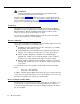
WARNING: Indicates the presence of a hazard that can cause severe or fatal personal injury if the hazard is not avoided. Carefully read the WARNING statement on page 2-7. Opening the system modules or backplane will expose you to hazardous voltages, which can cause severe or fatal personal injury. Also, read “Important Safety Instructions” on page 2-ii before performing any installation procedures.
Overview 1 Contents Managing the System Features and Capabilities System Components 1-1 ■ Control Unit System Modules System Capacity ■ Telephones System Telephones Standard Telephones 1-5 1-5 1-5 1-6 1-6 1-7 Auxiliary Equipment 1-7 ■ 1-7 1-7 1-8 1-8 ■ Industry-Standard Devices Limitations Connecting and Using Standard Devices Other Devices 1-2 1-4 1-i
Overview Managing the System This guide explains everything you need to know about using your PARTNER™ II Communications System. If you are responsible for managing the system—whether you are a receptionist, an office manager, or the “resident expert” on using it—you will find instructions and advice on the following topics: ■ Installing System Hardware.
■ Solving Problems. Appendix B provides information on solving problems and ordering additional accessories and equipment. If your system or telephones malfunction, you may be able to solve the problem by following the steps provided in the “Troubleshooting” section of that appendix. If you still need help, call the 24-hour AT&T Helpline at 1 800 628-2888. ■ Daily Operation. Depending on how your system is set up, you may need to oversee some of the system’s daily operations.
■ ■ Last Number Redial ■ Do Not Disturb ■ Privacy ■ Hold ■ Exclusive Hold ■ Transfer ■ Loudspeaker Paging ■ Call Forwarding ■ Direct Line Pickup Supports the following groups of extensions for flexibility in directing and answering calls: ■ Calling Groups allow users to ring or page (voice-signal) a group of extensions at once ■ Call Pickup Groups allow users to answer incoming calls ringing at any extension in a group ■ Extension Hunt Groups allow users to ring or page the first avail
System Components Modular hardware design makes the system easy to install and expand. Figure 1-1 shows the components of the system. A brief description of each component follows the figure. Figure 1-1.
Control Unit The control unit is the heart of the system; it is made up of one or two carriers, which house the system modules. A fully loaded system has two carriers, referred to as the primary carrier and the expansion carrier. Each carrier housing includes a backplane and a cover. All system modules slide into the backplane, which channels power to the system. The cover slides onto the front of the backplane after all the system modules have been installed.
Telephones System Telephones AT&T MLS- and MLC-model telephones are designed to make maximum use of the system’s features. They have several buttons in common: two volume control buttons, two intercom buttons, and the [ Feature ], [ Conf ], [ Transfer ], and [ Hold ] buttons. The five system phones and their additional features are: ■ ■ AT&T MLS-34D™ Telephone.
Standard Telephones Standard phones are industry-standard (non-proprietary) rotary or touch-tone phones, including feature phones with built-in feature buttons and lights. See “Industry-Standard Devices” in the following section for more information on standard phones. Auxiliary Equipment The system works with many telecommunications devices, not only system phones.
Connecting and Using Standard Devices You can connect a standard device so that it is on an extension by itself, or so that it shares an extension with another piece of equipment (either another standard device or a system phone). An extension with two devices connected to it is called a combination extension. For example, you can connect a standard touch-tone phone and an answering machine to the same extension.
■ In-Range Out-of-Building (IROB) protectors are required to prevent electrical surges from damaging your system when phones are installed in another building, but on the same continuous property. The system supports the AT&T 504A1 IROB protector, which provides coverage over a distance of 3,000 feet for standard phones and 1,000 feet for system phones. (For installation instructions, refer to the booklet packaged with the IROB protector.
Installing the Hardware 2 Contents Important Safety Instructions Installation Guidelines 2-1 Placement of Carriers and Modules Line and Extension Numbering ■ Connection of Telephones and Devices Combination Extensions 2-1 2-2 2-2 2-3 An Example System Setup Installation Procedures 2-4 ■ ■ ■ ■ ■ ■ ■ ■ ■ ■ Required Parts Installing the Carriers and Modules Connecting Lines and Extensions Assembling System Phones Desk Mounting Wall Mounting Connecting and Testing Telephones Connecting Paging and Mus
Important Safety Instructions Always follow these basic safety precautions when using the system: 1. Read and understand all instructions. 2. Follow all warnings and instructions marked on the product. 3. DO NOT block or cover the ventilation slots and openings. They prevent the product from overheating. DO NOT place the product in a separate enclosure unless proper ventilation is provided. 4. Never spill liquid on the product or drop objects into the ventilation slots and openings.
Installing the Hardware 2 This chapter explains how to install the system. It begins with general guidelines to consider before installation, followed by an example setup. It ends with step-by-step instructions for connecting and testing the components. Follow the instructions that apply to your setup. IMPORTANT: Before installation, record your setup choices in the System Planner, available separately. Installation Guidelines Placement of Carriers and Modules ■ Carriers.
Line and Extension Numbering Outside lines connect to the top two jacks on 206 modules and any jack on 400 modules. For each 206 module, the system assigns two lines and six extensions; for each 400 module, the system assigns four lines. The system numbers the lines from 01 through 24 (if you have the maximum number of lines), and numbers the extensions 10 through 57 (if you have the maximum number of extensions).
– Power Failure Operation. During a power failure, system phones will not work because they require power to operate. However, if standard phones are connected to extensions 10, 16, 22, 28, 34, 40, 46, or 52, they can place and answer outside calls on lines 1, 3, 5, 7, 9, 11, 13, or 15, respectively. Connect a standard phone to one or more of these extensions, either alone or combined with a system phone.
An Example System Setup These two pages show a control unit with two 206 modules and three 400 modules, giving the system a capacity of 16 outside lines and 12 extensions. Although your system will probably differ, this example will give you an idea of the types of equipment you can connect to it. In the example, system phones and industry-standard equipment are connected to ten extensions.
Installing the Hardware 2-5
Installation Procedures Before installing the system, be sure you read the safety instructions on page 2-ii. In addition, be sure you have the parts shown in Figure 2-3 (if not, call the Helpline). You will have up to four packages of system components; Figure 2-3 shows the contents of each package in the area marked by a dashed line.
Installing the Carriers and Modules Backplane Backplane 1 A) Hold the backplane against the wall. (If you are also installing the expansion carrier, plan to install it to the right of the primary carrier, leaving 6” to 24” between carriers.) Using the four screw keyholes in the backplane as a template, mark screw locations on the wall. Start four #12 screws, leaving the screw heads approximately 1/4” away from the wall. Slip the backplane onto the screws and tighten them.
Connecting Lines and Extensions 555-1343 555-1344 555-1345 555-1346 Network Interface Jacks 1 Test for dial tone at the network interface jacks before connecting outside lines. Connect a standard touch-tone or rotary phone to the first network interface jack. Lift the handset and listen for dial tone. Repeat for each network interface jack. (If there is no dial tone, contact your local telephone company before continuing.
Assembling System Phones Desk Mounting (stand required for MLS-34D; optional for other system phones) 1 A) Plug one end of the handset cord into the jack on the handset and the other end into the small jack on the left side of the base. If installing an MLS-34D, go directly to step 2 (skip 1B). B) Plug one end of the phone cord into the big jack on the bottom of the phone. Push the cord into place along the channel on the bottom of the phone.
Connecting and Testing Telephones 1 To connect a phone, plug the modular telephone mounting cord into a modular wall jack or directly into a 206 module extension jack. (If you are connecting a standard phone and its mounting cord is loose, use an AT&T D2R mounting cord instead.) To install two phones (or other devices) on a single extension jack, see the figure on page 2-3. Test the telephone for proper 2operation.
Connecting MLS-CA24 Intercom Autodialers One Autodialer Power Unit Wall Jack 1 To connect one Intercom Autodialer to a system phone: A) Unplug the phone’s modular telephone cord from the jack on the bottom of the phone and the wall jack, and save the cord for step B. Then, plug one end of the D8W cord, supplied with the autodialer, into the phone. Route the other end through the groove at the back of the autodialer and plug it into the OUT jack.
Replacing a System Module To replace a system module, first disconnect the AC power cord from the wall outlet, and then slide the control unit cover off the backplane. Place one hand on top of the module. With the other hand, grip the plastic bracket on the bottom front of the module, and use the middle finger to hold down the locking tab just below the bracket. Slide the module straight out, being careful not to strain the wires connected to the module.
Programming 3 Contents Alphabetical List of Programming Procedures Overview 3-1 ■ Initial System Setup Copy Settings ■ Changing Settings after Installation Changing the System Clock Adding New Lines Adding New Extensions 3-2 3-2 3-3 3-3 3-3 3-3 System Programming 3-4 ■ System Programming Options 3-ii Dialing Restrictions and Permissions Setting Up Groups of Extensions Night Service Setting Up Auxiliary Equipment System Speed Dialing ■ System Programming Procedures The Programming Overlays System
Alphabetical List of System and Telephone Programming Procedures For information on a programming procedure, see the page cited in this table. System programming procedures are identified by the procedure code following the procedure name (for example, #305 for Abbreviated Ringing). Telephone programming procedures show only the procedure name (they have no code).
Programming 3 Overview After you install the system hardware as described in Chapter 2, you can customize the system and individual telephones to meet the requirements of your business. This chapter explains how to use programming to accomplish that. There are two types of programming: ■ System Programming allows you to customize the system to meet the needs of your business.
Initial System Setup After installing the control unit, you set up the system using a combination of system and telephone programming procedures. However, before you program, you need to: ■ Compile a list of system extensions, along with the type of phone at the extension, and identify the lines to assign to each extension.
Changing Settings after Installation As your business grows or changes, you will probably need to change the way your system was originally programmed. Here are some examples: Changing the System Clock You may need to change or reset the system clock for daylight saving time, after a prolonged power failure, or after a complete system reset. To change the system clock, use the following procedures: ■ System Date (#101) to set the month, day, and year. ■ System Day (#102) to set the day of the week.
■ Outgoing Call Restriction (#401) to prevent the extension from making certain types of outgoing calls (on all system lines). ■ Disallowed List Assignment (#405) to assign one or more Disallowed Phone Number Lists to the extension. Use the Disallowed Phone Number Lists (#404) procedure to compile the lists of outside numbers that extensions cannot dial. ■ Allowed List Assignment (#408) to assign an Allowed Phone Number List to the extension.
Restricting Access to Outside Lines A user can access a line either by pressing a button on the phone or by dialing a feature code (Direct Line Pickup). If you do not want a user to access a specific line, use Line Access Restriction (#302) to control an extension’s access to a certain line.
■ Night Service causes after-hours calls to ring immediately at the extensions in the Night Service Group, regardless of Line Ringing during normal day operation. If you define a System Password, turning Night Service on also restricts outside calling by all extensions in the Night Service Group. See page 3-10 for details on Night Service.
Summary Table 3-1 summarizes the available dialing restrictions and permissions, showing how they can be combined in a variety of ways to customize an extension’s dialing privileges. Table 3-1.
Setting Up Groups of Extensions You can set up four types of extension groups: ■ Pickup Groups that let any user in the system answer outside calls for any extension in a group ■ Calling Groups that let users ring or page all extensions in a group simultaneously ■ Extension Hunt Groups that allow users to ring or page the first available extension in a group ■ Night Service Group that lets extensions in the group receive calls after hours. Pickup Groups The system can have up to four Pickup Groups.
■ Put the extensions of people with similar responsibilities in a Calling Group, so when a caller needs to talk with anyone in the group, the person simply dials a code instead of having to place separate intercom calls. Example: A car dealership puts all extensions for the sales staff into Calling Group 1. To talk to any salesperson, the sales manager simply places a ringing intercom call to the group by dialing the Calling Group dial code for that group ([ Intercom ] [ 7 ] [ 1 ]).
Night Service The Night Service feature allows you to change how a group of extensions operates after normal business hours. When Night Service is turned on, all incoming calls will ring immediately at the extensions in the Night Service Group, even if Line Ringing for those extensions is set for “delayed ring” or “no ring” during normal daytime use. Example: In a real estate office, all calls normally come through a receptionist.
Setting Up Auxiliary Equipment In addition to telephones, your system can include fax machines, answering machines, automated attendants, modems, doorphones, loudspeaker paging systems, and other auxiliary equipment. The following programming procedures help you manage auxiliary equipment: ■ Fax Machine Extensions (#601) lets you identify an extension on which a fax machine is installed.
■ AA/VMS Extensions (#607) identifies extensions on which you have installed an automated attendant. Automated attendants answer calls and route them to the appropriate extension based on caller responses to a recorded announcement. Also, use Transfer Return Extension (#306) to identify the extension to which the call should be routed if the destination extension does not answer.
System Programming Procedures System Programming requires an MLS-34D or MLS-12D phone at extension 10 or extension 11, with a programming overlay placed over the phone’s dial pad. System Programming procedures are identified by # and a three-digit code (for example, System Date is #101). In general, you can program the system in one of two ways: ■ Direct Method. With this method, you access a programming procedure directly by dialing the code for that procedure.
Figure 3-2.
Figure 3-3.
System Programming Reference System Programming changes settings for the system as a whole, or for individual lines or extensions. You can also use System Programming to set up dialing restrictions, define groups, and set up optional equipment.
EXTENSIONS LINES DIAL MODE Identifies individual lines as touch-tone or rotary. You may also need to adjust the Rotary Dialing Timeout (#108). DIAL #201 DIAL a line number DIAL 1 = Touch-Tone ✔ 2 = Rotary PRESS [ Next Item ] to program another line HOLD DISCONNECT TIME Determines the signal that the system uses to detect when a caller on hold hangs up.
System Programming Reference System Programming changes settings for the system as a whole, or for individual lines or extensions. You can also use System Programming to set up dialing restrictions, define groups, and set up optional equipment.
GROUPS PICKUP GROUP EXTENSIONS Assigns extensions to a Pickup Group, Outside calls to a Pickup Group can be picked up by any user in the system. DIAL #501 DIAL a group number (1 to 4) DIAL an extension number 1 = Assigned to group DIAL 2 = Not assigned to group ✔ PRESS [ Next Item ] to assign another extension To program another group: PRESS [ Next Procedure ] [ Prev Procedure ], enter a new group number, and repeat above steps CALLING GROUP EXTENSIONS Assigns extensions to a Calling Group.
System Speed Dial Programming Reference From extension 10 or 11, you can store up to 60 outside numbers as System Speed Dial numbers. Once System Speed Dial numbers have been stored, any user can dial a number automatically by pressing [ Feature ] + a two-digit code (from 20–79). NOTE: In addition, each extension can store up to 20 Personal Speed Dial numbers (80–99) for the private use of the user at the extension; see page 3–26 for programming instructions.
Telephone Programming System telephones are ready to use when they are installed, but they can be customized to meet the needs of your business and individual users. This customization is accomplished through telephone programming. Telephone Programming Options Automatic Line Selection When a user lifts the handset of a telephone, the system chooses an idle line automatically. The Automatic Line Selection procedure sets the order in which the system looks for an idle line.
Personal Speed Dialing Personal Speed Dial numbers are outside phone numbers that a user dials by pressing [ Feature ] (or [ # ] on a standard phone) plus a two-digit code. Unlike System Speed Dial numbers, which are available to all users in the system, Personal Speed Dial numbers are available only at the extension for which they are programmed.
Programming a Receptionist’s Extension If you set up a centralized telephone answering position at extension 10, use the following settings to customize it: ■ Immediate call answering. If the receptionist should answer all calls, assign all lines (#301) to extension 10. Set Line Ringing for all lines at extension 10 to “immediate ring;” set the lines assigned at each user’s extension to “delayed ring” or “no ring. ” ■ Backup call answering.
Telephone Programming Procedures The rest of this chapter gives step-by-step instructions for each Telephone Programming procedure. To program a phone from extension 10 or 11, use the instructions at the top of page 3-26. To program at the extension, use the instructions at the bottom of page 3-27; then go to the appropriate box on pages 3-26 and 3-27 for instructions on programming an individual feature.
MLS-34D Phone Line/ Programmable Buttons Any unused Iine button is programmable MLS-12D Phone MLS-12 Phone Programmable Buttons Programmable Buttons (without lights) (without lights) Line/ Programmable Buttons Line/ Programmable Buttons Any unused line button is programmable Any unused line button is programmable MLC-6 Phone MLS-6 Phone Line/Programmable Buttons Any unused line button is programmable Figure 3-4.
Telephone Programming Reference Centralized Telephone Programming Use Centralized Telephone Programming to program features or store telephone numbers for individual extensions. Automatic Line Selection and Line Ringing must be programmed from extension 10 or 11 (using Centralized Telephone Programming); all other features can be programmed on a system phone at the user’s extension (see “Extension Programming” on next page).
DIAL-CODE FEATURES LAST NUMBER REDIAL Automatically redials the last outside number dialed. PRESS a programmable button PRESS [ Feature ][0][5] CONFERENCE DROP Drops the last outside party added to a conference call, without disconnecting the other parties. PRESS a programmable button PRESS [ Feature ] [ 0 ] [ 6 ] PRIVACY Prevents other extensions that share a line from joining telephone conversations.
Using Telephones 4 Contents System Telephones ■ ■ ■ ■ ■ Buttons and Indicators Lights Ringing Patterns Dial Tones Using the Handset, Speaker, and Microphone Hands-Free Answer on Intercom (HFAI) Speakerphone Performance Tips 4-1 4-2 4-4 4-5 4-5 4-5 4-6 4-6 Standard Telephones 4-7 Ringing Patterns Dial Tones ■ Using the Switchhook ■ Limitations ■ Feature Phones 4-7 4-8 4-8 4-8 4-9 Combination Extensions Dial-Code Features Using Your Telephone 4-9 ■ ■ ■ ■ ■ ■ ■ ■ ■ ■ ■ Placing a Call Answering a
Using Telephones 4 System Telephones System phones have some common buttons and indicators. The following pages explain where they are and how they work. Instructions for using dial-code features on system and standard phones begin on page 4-11, and call handling instructions begin on page 4-14.
Buttons and Indicators MLS-34D Display Dual-Purpose Line/Programmable Buttons (32 with lights) Intercom Buttons (2) MLS-12D Display Programmable Buttons MLS-12 (6 without lights) Dual-Purpose Line/Programmable Buttons (10 with lights) Intercom Buttons (2) The following buttons and displays appear on system phones. (Some controls and indicators are not available on all phones.) Display.
MLS-6 Line/Programmable Buttons (4) Intercom Buttons (2) MLC-6 Earpiece Volume Control Line/Programmable Buttons Intercom Buttons Spkr (Speaker) (all models except the MLC-6). Press to talk without lifting the handset. Turns on speaker and microphone (if available), so you can dial or have a conversation without lifting the handset. Mic (Microphone) (MLS-34D, MLS-12D, and MLS-12 only). Leave on to use Hands-Free Answer on Intercom feature.
Lights Each line button has a green light and a red light. The meaning of these lights varies, depending on whether a button is used to access an outside line, is programmed with a dial-code feature, or is programmed with an Intercom Auto Dial number. (Auto Dial buttons for fax extensions show additional information; these “Fax Management” buttons are described in Chapter 5.) Table 4-1 shows the meanings of the various light patterns for each possible button assignment. Table 4-1.
Ringing Patterns You can tell what kind of call you are receiving by the way your telephone rings. ■ A single ring (ring . . . ring . . . ring . . . ) means that you are receiving an outside call. ■ A ring and a beep (ring BEEP . . . ring BEEP . . . ring BEEP . . . ) means that someone is calling you from another extension. If you have a system phone with a display, the caller’s extension number will show on the display. ■ A ring and two beeps (ring BEEP BEEP . . . ring BEEP BEEP . . . ring BEEP BEEP .
■ If you are already on a call, you can switch from the handset to the speaker and microphone (on an MLS-34D, MLS-12D, or MLS-12 phone) by pressing [ Spkr ] and hanging up the handset. Conversely, if you are using the speaker and microphone and want to switch to the handset, lift the handset and the speaker and microphone will turn off. ■ Use the Hands-Free Answer on Intercom (HFAI) feature to answer voice-signaled calls without lifting the handset (see below).
■ If you have difficulty hearing the other party, increase the speaker volume. If the difficulty persists, lift your handset to continue the conversation. ■ In conference rooms, a separate speakerphone (such as the AT&T S203 Speakerphone) is recommended, since the built-in speaker on a system phone is designed for individual use.
Dial Tones Standard phones have two different dial tones: ■ Outside dial tone is generated by your local telephone company to indicate that you are connected with an outside line. ■ Intercom dial tone is generated by the system to indicate that you are connected with an inside line. You hear this dial tone when you are making an inside, or intercom, call. To hear the difference between the two dial tones, lift the handset. The dial tone you hear is an intercom dial tone.
Feature Phones A feature phone is a standard telephone that has feature buttons in addition to the regular 12-key dial pad. For example, there are feature phones that have programmable auto dial buttons, last number redial buttons, hold buttons, and built-in speakerphones. Most of the features on these phones will work with the system. You can use most of the system’s dial-code features from a feature phone, and program them onto a feature phone button.
4-10 ■ Both phones share the same voicepath; that is, when either phone is busy, the extension is busy. ■ The lights on the system phone show what the standard telephone is doing as well as what the system phone is doing. For an explanation of light patterns, see “Lights” at the beginning of this chapter. ■ Calls ring at both phones. ■ You can handle a call on the standard telephone by pressing buttons on the system telephone.
Dial-Code Features Dial-code features are features that are accessed by a dial code. They include such features as Exclusive Hold, Conference Drop, and Last Number Redial. A complete list of dial-code features is shown in Table 4-2, which starts on this page. In general, you can use a dial-code feature in either of two ways: ■ Dial the code manually. For example, to use Last Number Redial on a system phone, press [ Feature ] [ 0 ] [ 5 ]; to use it on a standard phone, press [ # ] [ 0 ] [ 5 ].
Dial-Code Feature To Use Manually on a . . . System Phone Standard Phone To Use When Programmed on a Button Last Number Redial Dial [ Feature ] [ 0 ] [ 5 ] Dial [ # ] [ 0 ] [ 5 ] Press the button Dial [ Feature ] [ 0 ] [ 6 ] Not available as a dial-code feature, but you can press the switchhook instead Press the button Not available Not available Press the button to turn Privacy on; press it again to turn it off.
Dial-Code Feature Call Forwarding Forwards all intercom, outside, and transferred calls from your extension to a destination extension. You can activate Call Forwarding from any extension. Programming this feature on a button with lights will let you see at a glance if your calls have been forwarded. Also, your system phone will beep once each time a call is forwarded from your extension to indicate Call Forwarding is active. (You will not hear this beep if Do Not Disturb is turned on.
Using Your Telephone The charts below explain how to handle calls with both system and standard phones. When prior programming is required, the page number where you can find programming instructions is shown in the left column. NOTE: The instructions in the following tables assume standard phones have been programmed with Automatic Line Selection set to “Intercom first.” This means when a user on a standard phone lifts the handset, the user will automatically hear intercom dial tone.
To reserve an outside line If a line you want to use is busy (steady red light), you can reserve it and your phone will beep when the line becomes free. The Line Reserve feature is useful when you share a line—such as a WATS line—with other people. On a System Phone* On a Standard Phone 1. Press the busy line button without lifting the handset or touching [ Spkr ]. This feature is not available. 2. When the line is free and your phone beeps, lift the handset and dial the number.
To enter a System Password to override dialing restrictions See page 3-18 for programming instructions. You cannot use a System Password on an MLC-6 phone. On a System Phone* On a Standard Phone Before lifting the handset or turning on the speaker ... This feature is not available. 1. Press [ Hold ]. 2. Enter the password. The password overrides all dialing restrictions but not Line Access Restriction (#302). (The System Password will not appear on display phones.) 3.
On a System Phone* On a Standard Phone To ring or page all extensions in a Calling Group 1. Lift the handset and press [ Intercom ] (in either order). You hear the intercom dial tone. 1. Lift the handset. You hear the intercom dial tone. See page 3-19 for instructions on setting up a Calling Group. 2. To make a ringing call, dial [ 7 ]. You can program [ Intercom ] [ 7 ] and a group number from 1 to 4 onto a programmable button to make a Group Call with a single touch.
Answering a Call On a System Phone* On a Standard Phone To answer a call When the telephone is ringing ... When the telephone is ringing... You can program Direct Line Pickup onto a button. See page 3-27 for programming instructions. 1. Lift the handset. You are connected to the incoming call. If more than one line is ringing, you are connected to the line that has been ringing longest. 1. Lift the handset. You are connected to the incoming call.
To answer a call ringing at another extension The call can be an outside call, an intercom call, or a transferred call, and can be on a line not assigned to your extension. See page 3-19 for instructions on programming a Pickup Group. On a System Phone* On a Standard Phone When an extension in the system is ringing (and the extension number is known) ... When any extension in the system is ringing (and the extension number is known)... 1. Lift the handset. 1. Lift the handset.
Putting a Call on Hold To put a call on hold (anyone can retrieve it) Only one party on an intercom call can put the call on hold. If both parties try to put the call on hold, the call will be disconnected. To put an outside call on Exclusive Hold (only you can retrieve it) On a System Phone* On a Standard Phone 1. Press [ Hold ]. The light next to the line button winks green. 1. Press the switchhook down once rapidly. You hear the intercom dial tone. The call is on hold.
Transferring a Call On a System Phone* On a Standard Phone To transfer a call To transfer a call with one button touch ... This feature is not available. You can transfer both outside and intercom calls to other system extensions. You cannot transfer calls to a Calling Group, but you can transfer calls to a Hunt Group. 1. While on a call, press the Auto Dial button assigned to the extension you want to transfer the call to. (There is no need to press [ Transfer ] or [ Hold ].
Making a Conference Call A conference call connects up to five parties (including the originator) in a single call. You can connect both outside calls and intercom calls in a conference call, but the call cannot include more than two outside parties. You cannot have two outside parties on a call if your system is programmed for Outside Conference Denial (#109). See Chapter 3 for details. You can use System Speed Dial, Personal Speed Dial, or Auto Dial numbers to add parties to the conference.
Joining a Call Joining is adding yourself to a call in progress, the same way you do on a home telephone by picking up an extension. (This is different from conferencing, in which the originator “pulls you into” the call.) If you call on an outside line, up to three more system extensions can join you on the call (for a total of one outside and four inside parties).
Loudspeaker Paging On a Standard Phone On a System Phone* To make an announcement over a loudspeaker paging system The system supports all AT&T paging systems. If you have a paging system other than an AT&T PagePac6® or PagePac6 Plus, follow the manufacturer’s instructions. You can program [ Intercom ] [ 7 ] [ 0 ] on a system phone, see page 3-27. 1. Lift the handset and press [ (in either order). Intercom ] On a touch-tone phone only: 1. Lift the handset and dial [ 7 ] [ 0 ]. 2. Dial [ 7 ] [ 0 ].
Using Auxiliary Equipment 5 Contents Fax Machines ■ ■ ■ ■ ■ Using Fax Machines Fax Management Feature Transferring a Call to the Fax Machine Using the Fax Machine’s Notify Feature Setting Up Fax Machines Restricting Dialing from a Fax Machine Single Fax Machine Fax Line Saver Send and Receive Fax Machines 5-1 5-1 5-1 5-2 5-3 5-3 5-3 5-4 5-4 5-4 Answering Machines 5-6 ■ Single Answering Machine Multiple Answering Machines ■ Personal Answering Machine 5-6 5-6 5-8 Modems 5-9 Stand-Alone Modem for
There are many ways to set up auxiliary equipment—the setup you choose depends upon your needs and the number of devices you have. This chapter presents the most common setups. This chapter does not cover how to physically connect the equipment, or how to perform each programming procedure. See Chapter 2 for installation instructions and Chapter 3 for programming instructions.
Using Auxiliary Equipment 5 Fax Machines This section presents several ways that you can set up fax machines to work with your system. It includes instructions for programming and using a Fax Management button on a system phone (in order to monitor the status of a fax machine and transfer calls to it with a single touch), transferring calls to the fax machine extension, and using an AT&T fax machine’s Notify button.
Table 5-1. Fax Management Button Light Patterns Light Pattern Indicates... Off Fax idle. Red broken flutter Fax trouble. The fax machine is not answering. If broken flutter occurs because the fax machine is out of paper, refill the paper. The light clears the next time the machine transmits or receives a call. If the machine takes longer than four rings to answer, the light shows fax trouble; when the machine does answer, the light changes to fax busy (steady red). Red steady Fax busy.
Using the Fax Machine’s Notify Feature Some AT&T fax machines (for example, models 5300, 5350, 9025 Plus, and 9035 Plus) have a feature called Notify. After such a machine receives a fax call, it automatically dials a number and plays a recorded message, such as, “You have just received a fax.
Single Fax Machine The single fax machine setup (shown in Figure 5-1) is good for moderate traffic. The fax machine has its own line (Line A), the number of which is published as the fax number. (The fax line can be used by other phones when all other lines are busy.) The fax machine is connected to its own extension (extension X). To use: The fax machine automatically answers all calls that come in on the fax line.
Fax Line A To program: 1. Use Line Assignment (#301) to assign only line A to extension X. 2. Set Automatic Privacy (#304) for extension X to “on.” 3. Use Fax Machine Extensions (#601) to designate extension X as a fax extension. 4. Remove extension X from all Calling Groups (#502), all Pickup Groups (#501), the Night Service Group (#504), and all Hunt Groups (#505). 5. Set Line Ringing for line A on extension X to “immediate ring.” (On all other extensions, set line A to “delayed ring” or “no ring.”) † 6.
Answering Machines You can use an answering machine to answer calls at night when no one is around, or during business hours when no one can get to the phone. If you have an AT&T answering machine with the Call Intercept feature, you can pick up a call that has been answered by the answering machine by joining the call from any system phone. When you do so, the system sends the answering machine a signal that makes it hang up.
■ From outside the system, call in on any line assigned to the machine. When the machine answers, dial its message retrieval code. Note, however, that when calling in from outside, you can only retrieve messages from the first machine that answers. Lines Telephone (optional) CONTROL UNIT Ext X 267F2 Bridging Adapter (optional) ANS MACH To program: 1. Use Line Assignment (#301) to assign all the lines to extension X that you want the answering machine to cover. 2.
Personal Answering Machine A personal answering machine is used to answer all the calls that ring on the lines at a certain extension (Figure 5-6).
Modems There are several ways to use modems with your system, as described below. Note: Modems can connect directly to an extension jack without an adapter. Stand-Alone Modem for Placing Calls Only A modem and a terminal allow you to dial out and connect to computer bulletin boards and other data services. This setup, which lets you dial out but not receive calls, is shown in Figure 5-7.
Lines 267F2 Bridging Adapter (optional) CONTROL UNIT Modem PC or Terminal Ext X Telephone (optional) To program: 1. Use Line Assignment (#301) to assign one or more lines to extension X. 2 .Set Automatic Extension Privacy (#304) for extension X to “on.” 3. Remove extension X from all Calling Groups (#502), all Pickup Groups (#501), the Night Service Group (#504), and all Hunt Groups (#505). 4. Set Automatic Line Selection for extension X to “outside lines first.” 5.
Automated Attendants An automated attendant answers calls and redirects them to a specified extension or to a Hunt Group (based on the digits a caller dials after listening to a list of choices in a recorded greeting). For example, your company might have an automated attendant answer calls and tell callers to press 1 for Sales, 2 for Parts, 3 for Service, and so on. Automated Attendant Used as Backup for Receptionist One common use of an automated attendant is as a backup for a receptionist.
Credit Card Scanners Many retail businesses and restaurants use credit card scanners to get instant approval of credit card purchases. The system allows your credit card scanners to share the lines in your system (as shown in Figure 5-10). You can install the credit card scanner on an extension by itself, or combine it with a system phone or a standard phone on the same extension. To use: When you make a call on the credit card scanner, an outside line is automatically selected.
Night Service with Auxiliary Equipment You can set up modems, fax machines, and answering machines to receive calls automatically after hours. When Night Service is on, calls ring immediately at the appropriate extensions, so that no human intervention is required to transfer calls to the fax, modem, or answering machine. When Night Service is off, you can use the auxiliary equipment lines for normal business purposes, so that lines are dedicated to auxiliary equipment only after hours.
Call Reporting Devices (SMDR) SMDR (Station Message Detail Recording) is a call reporting feature that provides records of call activity. Call reporting information provides you with the ability to: ■ Detect any unauthorized calls ■ Bill clients or projects ■ Reduce telephone costs by identifying the need to change telecommunications services (like adding a WATS line for calls to a particular area code) Call reporting information is recorded as calls occur.
A “*” character prints as the last digit of a dialed number if the called party hangs up before the originator, or a “?” prints if the number of digits dialed exceeds the 15 digits that the Called Number field can hold. ■ Duration. The duration of the call is shown in hh:mm:ss format, where hh is the hour, mm is the minutes, and ss is the seconds. ■ Line Number. This is the outside line (01–24) that was used to make or receive the call. ■ Station (Extension).
Call Accounting Devices You can send call information to a call accounting device if you want to further analyze call activity. The device stores rate table information and processes the information it receives into meaningful reports that can help you optimize your communications system. For example, you can use it to determine the best combination of local and long distance lines for your business.
Speed Dial Form A This appendix contains a Speed Dial Form to be photocopied and handed out to system users. It provides space on which to write System and Personal Speed Dial numbers. For instructions on programming System Speed Dial numbers, see Chapter 3 in this guide. We suggest you fill in a photocopy of the form, leaving the blank original in the book, in case you need to distribute revisions in the future.
PARTNER™ II Communications System AT&T To Dial ● On MLS- or MLC-model telephone, press [ Feature ] + Code ● On standard touch-tone telephone, press [ # ] + Code while receiving intercom dial tone.
Maintenance and Customer Support B Maintenance Your system is designed to provide trouble-free performance without any special maintenance procedures. To reduce the risk of accidental damage: ■ Keep the system modules in an area free of dust, smoke, and moisture, and do not block the air vents by placing objects on top of the system carriers. ■ Do not place telephones near a heating duct, radiator, or other heat source, and do not drop or expose them to excessive shock or vibration.
In Case of Difficulty If you should have a problem with your system, you may be able to solve it yourself by following the appropriate troubleshooting procedures described in this appendix.
Troubleshooting The charts on pages B-3 to B-7 describe various difficulties that might occur, possible causes for the difficulty, and procedures you can follow to try to solve the problem yourself. Table B-2. Troubleshooting Problem Possible Cause Do This If... Then... 1. All Phones Dead: No Dial Tone or Lights 1. Control unit not receiving power. Make sure the control unit’s power cord is plugged securely into the wall outlet.
Do This If... Then... Find out if you have touch-tone or rotary service and set the Dial Mode (#201) to “touch-tone” or “rotary.” You can make a call, The problem is solved. The Dial Mode is already set correctly, Go to Possible Cause 2. 2. Someone changed your Outgoing Call Restriction settings. Find out: were you able to make a call without any trouble before? You were able to call on the phone before and no one changed your Outgoing Call Restriction settings, Go to Possible Cause 3. 3.
Do This If... Then... Be sure the device is set to answer correctly. The optional device was set properly, Check Line Ringing. machine, or modem answers when it should not. If the device answers before it should, adjust it to answer on a later ring. If the device should not answer calls at all, turn its auto-answer feature off. Refer to the device’s user manual.
Problem Possible Cause Do This If... Then... 9. Phone Rings Back After Intercom Call with No One at Other End 1. The switchhook on a standard phone is accidentally pressed and released, causing a call to ring back. Always replace the handset carefully. The problem is not solved, Go to Possible Cause 2. 2. Automatic Line Selection is programmed incorrectly. If one of the phones involved is a standard single-line rotary or touch-tone phone, program its Automatic Line Selection to “intercom first.
Problem Possible Cause Do This If... Then... 13. Phone Display Does Not Work Date, day, and time do not display properly. Re-enter the date, day, and time using System Programming (#101, #102, and #103). The display works, Problem is solved. The display still does not work, Follow procedure for “Other Problems with Phones.” 14. System Phone in Combination, Extension Does Not Work 1. System phone is plugged into wrong jack of bridging adapter. Plug system phone into the correct jack (see Fig.
Repair Information In-Warranty Repairs If you purchased or leased your system directly from AT&T, AT&T will repair it free of charge during the one-year warranty period. Simply call the Helpline at 1 800 628-2888 and ask for service. Business-Day service is standard during the warranty period for both the control unit and system phones. Business-Day service is performed during normal business hours.
If you purchased your system directly from AT&T, AT&T will perform warranty repair in accordance with the terms and conditions of the specific type of AT&T maintenance coverage you selected. A written explanation of AT&T’s types of maintenance coverage may be obtained from AT&T by calling 1 800 247-7000. If you purchased your system from an AT&T-authorized reseller, contact your reseller for the details of the maintenance plan applicable to your system.
Product Ordering Information Ordering additional telephones and modules, accessories, and replacement parts for your system is convenient. Table B-1 (on the next page) shows where you can buy system components in the United States.
To use Table B-1, first locate the item you want. A triangle ( ▲ ) indicates where you can obtain it. SOURCE (U.S.
C Specifications Capacities ■ ■ ■ ■ ■ ■ Dimensions and Weights (approx.
Extension Jack Specifications ■ ■ ■ PAGE Jack Specifications ■ ■ ■ Environmental Requirements— Control Unit ■ ■ ■ ■ ■ ■ ■ Electrical Requirements ■ ■ ■ Requirements for Out-of-Building Extensions ■ MLS-model telephone: two AT&T 504A1 protectors Standard device: one AT&T 504A1 protector plus one carbon block protector ■ 68000 microprocessor, 64K RAM, 256K ROM ■ 12 mHz, 128K RAM, 64K ROM ■ ■ ■ ■ ■ ■ Specifications 90–130 VAC, 50–60 Hz, 3-prong outlet separate ground, separately fused at 15
FCC Information D Federal Communications Commission (FCC) Interference Information This equipment has been tested and found to comply with the limits for a Class A digital device, pursuant to Part 15 of FCC rules. These limits are designed to provide reasonable protection against harmful interference when the equipment is operated in a commercial environment.
■ ■ The appropriate registration number and ringer equivalence number (REN), which can be found on the right hand side of the primary carrier. The facility interface code, which is O2LS2. You must also notify your local telephone company if and when this equipment is permanently disconnected from the line(s).
Index A C Abbreviated Ringing (#305), 3-17 Accessories, 1-8, B-11 Adding lines and extensions, 3-3 Allowed List Assignment (#408), 3-18 Allowed Phone Number Lists (#407), 3-6, 3-18 Amplified handset, 1-9, B-11 Answering a call at your extension, 4-18 ringing at another extension, 4-19 Answering machines, 5-6 to 5-8 Assembling system phones, 2-9 Attendant/VMS Extensions (#607), 3-19 Attendants, automated, 1-7, 3-19, 5-11 Audio source, installing, 2-10 Auto Dial buttons, 3-22 Auto Dial numbers intercom (in
programming, 3-22, 3-26 to 3-27 using, 4-11 to 4-13 Dial Mode (#201), 3-17 Dial tones, outside vs.
HFAI (Hands-Free Answer on Intercom), 4-6 Hold button, 4-2 Hold Disconnect Time (#203), 3-17 Hold, Exclusive, 3-26, 4-11, 4-20 Holding a call, 4-20 Hotline (#603) programming for, 3-11, 3-19 standard phone used as, 2-3 Hunt Groups (see Extension Hunt Groups) I Immediate call answering, 3-23 Immediate ring, 3-21, 3-23 Indicators, system telephone, 4-2 Industry-standard devices (see Standard devices) In-Range Out-of-Building (IROB) protectors, 1-9, B-11, C-2 Inside call, making an, 4-16 Installation 267F2 br
MLS-34D telephone for receptionist, 3-23 programming overlay, 3-14 MLS-model telephones, 1-6, 4-2, B-11 Modems, 5-9 to 5-10 Modular telephone cords, connecting, 2-8 Modules 200, 1-5, 2-7 206/400, 1-5, 2-1, B-11 description, 1-5, 2-1 expansion processor, 1-5, 2-1, B-11 installing, 2-7 primary processor, 1-5, 2-1, B-11 removing and replacing, 2-12 Monitoring call activity, 3-23, 5-14 to 5-16 Mounting cords, connecting, 2-8 Mounting locations, 2-9 Music-on-hold description, 1-8 installing audio source, 2-10 ja
telephone, 3-21, 3-24 to 3-27 Q Quick Reference cards (for system phones), iv Quick Reference (programming), Inside back cover R Recall programming feature on a button, 3-26 programming function in phone number, 3-20 using, 4-11 Recall Timer Duration (#107), 3-16 Receptionist extension, 3-23 Redial, Last Number, 3-27, 4-12 Redial, Save Number, 3-26, 4-11 Removing modules, 2-12 REN (Ringer Equivalence Number), 1-7 Repair, B-8 Repertory dialers, 1-9 Replacement parts, B-11 Replacing modules, 2-12 Reserving
using, 4-16 System phones assembling, 2-9 buttons, 4-2 to 4-3 call handling, 4-14 to 4-23 connecting, 2-10 definition, iv dial tones, 4-5 labeling sheets, 3-25 lights, 4-4 mounting, 2-9 overview, 1-6 ringing patterns, 4-5 speaker, 4-5 to 4-7 testing, 2-10 using, 4-14 to 4-24 System Planner, iv System programming (see also Programming) alphabetical list of procedures, 3-ii changing, 3-16 to 3-17 general instructions, 3-4 individual procedures, 3-16 to 3-20 initial, 3-2 methods of, 3-13 options, 3-4 to 3-12 o
Centralized Telephone Programming Quick Reference Place the Programming Overlay on the dial pad of the system display phone at extension 10 or 11 TO ENTER PROGRAM MODE PRESS [ Feature ] [ 0 ] [ 0 ] PRESS [ System Program ] PRESS [ System Program ] PRESS [ Central Tel Program ] DIAL the extension number to be preprogrammed Buttons on which lines are assigned for the extension light up to show the current Line Ringing setting; remaining buttons can be programmed with Auto Dial numbers or features TO PR
System Programming Quick Reerence Place the Programming Overlay on the dial pad of the system display phone at extension 10 or 11 TO START SYSTEM PROGRAMMING TO END SYSTEM PROGRAMMING PRESS [ Feature ] [ 0 ] [ 0 ] PRESS [ Feature ] [ 0 ] [ 0 ] PRESS [ System Program ] TO USE A SPECIFIC PROCEDURE PRESS [ System Program ] DIAL [ # ] and three-digit procedure code #728—shown below in dashed boxes—are skipped when cycling. Example: [ # ] [ 1 ] [ 0 ] [ 1 ] for System Date System DIAL MODE (p.
SYSTEM RESET – PROGRAMMING SAVED IMPORTANT: Using this procedure disconnects any active calls but retains system settings. Use it only if the system fails to function correctly after a power failure or down period. DIAL #728 Groups Dialing Restrictions and Permissions OUTGOING CALL RESTRlCTION (p. 3-18) DIAL #401 DIAL an extension number DIAL 1 = No Restriction ✔ 2 = Inside (intercom) Only 3 = Local (intercom and local) Only PRESS [ Next Item ] to program another extension TOLL CALL PREFIX (p.
518-455-310 Graphics © AT&T 1988