AT&T ® PARTNER II Communications System Release 3 Programming and Use
Copyright © 1992 AT&T All Rights Reserved Printed in U.S.A. AT&T 518-455-311 Issue 1 July 1992 Notice Every effort was made to ensure that the information in this book was complete and accurate at the time of printing. However, information is subject to change. Federal Communications Commission (FCC) Interference Notice This equipment has been tested and found to comply with the limits of a Class A digital device, pursuant to Part 15 of FCC rules.
Contents 1 About This Guide iii Overview 1-i 1-ii 1-1 1-2 1-6 ■ ■ ■ ■ 2 Programming ■ ■ ■ ■ ■ ■ ■ ■ ■ 3 Overview Hardware Considerations Initial System Setup Changing Settings after Installation Changing Settings to Support PBX or Centrex Services System Programming Options Using System Programming Telephone Programming Options Using Telephone Programming Learning About Telephones ■ ■ ■ ■ 4 Important Safety Instructions Features and Capabilities System Components Auxiliary Equipment System Te
■ ■ ■ ■ ■ PARTNER MAIL PARTNER Attendant Credit Card Scanners Night Service with Auxiliary Equipment Call Reporting Devices (SMDR) 4-15 417 4-18 4-19 4-20 5 Feature Reference 5-i 6 Troubleshooting 6-i 6-1 6-1 6-2 ■ ■ ■ When You Need Help Power Failure Operation Problems and Solutions A Specifications A-1 B Maintenance, Repair, and Ordering Information B-1 C FCC Information C-1 GL Glossary GL-1 IN Index IN-1 Programming Quick References Inside back cover ii
About This Guide Purpose This guide is intended for the system manager. It explains what the PARTNER® II Communications System can do, provides instructions for programming and using the system, and shows you how to get the most out of its many features and capabilities. How to Use This Guide For information on the following topics, refer to the appropriate chapter: ■ Getting Acquainted. Chapter 1 provides an overview of system features and hardware components. ■ Programming the System.
■ Solving Problems. Chapter 6 provides information on solving problems if your system or telephones malfunction. Once you are experienced with the system, use the Table of Contents or Index to locate the information you need. Throughout this guide, feature names are printed in bold so you can easily look up the name in Chapter 5, “Feature Reference,” for additional information on the feature.
Overview 1 Contents Important Safety Instructions Features and Capabilities System Components ■ ■ Control Unit System Modules System Capacity Telephones System Telephones Intercom Autodialers Standard Telephones Auxiliary Equipment ■ ■ Industry-Standard Devices Requirements Connecting and Using Standard Devices Other Devices 1-ii 1-1 1-2 1-2 1-4 1-4 1-5 1-5 1-5 1-6 1-6 1-6 1-6 1-6 1-7 1-i
Important Safety Instructions Always follow these basic safety precautions when using the system: 1. Read and understand all instructions. 2. Follow all warnings and instructions marked on the product. 3. Never spill liquid on the product or drop objects into the ventilation slots and openings. Doing so may result in serious damage to the components. 4. Repair or service must be performed by a qualified repair person. 5. The product is provided with a three-wire grounding type plug.
Overview 1 Features and Capabilities The following list provides an overview of the system’s features: ■ Full line of MLS- and MLC-model system phones, providing access to multiple lines from a single phone at each extension. ■ Programmable buttons on system phones, providing one-touch access to system features simply by pressing the button. ■ Modular connections to the control unit, making it easy to reconfigure your system or to add lines and/or extensions as your business grows.
■ Centrex or PBX operation support—including one-touch dialing of feature access codes on system phones. ■ Power failure operation with standard phones, allowing you to make and receive calls during a power failure while retaining programmed equipment settings for up to four days. (An optional Uninterruptible Power Supply, or UPS, is also available to allow full equipment operation during a power failure.
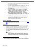
CONTROL UNIT 206 Module Circuit Breakers Primary Carrier Main Circuit Breaker 400 Modules 206 Modules Primary Processor Module Grounding Screw Extension Processor Module Outside Line Jacks Outside Line Jacks Power Indicators (LEDs) Expansion Carrier Main Circuit Breaker PAGE Jack SMDR Jack Extension Jacks (206 modules only) MUSIC ON HOLD Jack (for RCA phono plug) Expansion Cable SYSTEM PHONES Optional Devices (that connect to the control unit) Power Indicators (LEDs) Optional Devices (th
System Modules The following system modules can be installed in your system: ■ Primary Processor Module provides the software intelligence that controls the system’s features. It has jacks for a music-on-hold audio source, a loudspeaker paging system, and a call reporting (SMDR) device, such as a printer. It also has a green-wire grounding screw to properly ground the control unit.
Telephones System Telephones This guide refers to AT&T telephones specifically designed to work with the PARTNER II system as system phones. These include the MLS-34D, MLS-18D, MLS-12D, MLS-12, MLS-6, and MLC-6 model telephones. System phones have several buttons in common: volume control buttons, and the [ Feature ], [ Conf ], [ Transfer ], and [ Hold ] buttons.
Standard Telephones You can also use industy-standard single-line rotary or touch-tone telephones, including feature phones with built-in feature buttons and lights, with the system. This guide refers to such telephones as standard phones. AT&T-certified standard phones, such as the 8110, are recommended. “Industry-Standard Devices” in the following section provides more information on standard phones.
Other Devices In addition, you can connect the following devices to your system: ■ PARTNER MAIL allows callers to reach a desired extension or group without receptionist assistance and prompts callers to leave messages at unanswered or busy extensions, In addition, system subscribers can retrieve messages left in their mailboxes, send messages to other subscribers, and record their own personal greetings.
Refer to the manufacturer’s instructions packaged with the device for installation and usage information. In addition, the PARTNER II Communications System Installation guide provides installation instructions. Chapter 4 of this guide provides information on setting up devices to work with the system.
Programming 2 Contents Overview Hardware Considerations Initial System Setup ■ ■ ■ ■ Setting the System Clock Assigning Lines Customizing Extensions Copy Settings Changing Settings after Installation ■ ■ ■ ■ Changing the System Clock Adding New Lines Adding New Extensions Swapping Extensions Changing Settings to Support PBX or Centrex Services ■ ■ ■ Recall Setting Dialing Restrictions Speed Dial and Auto Dial Numbers System Progamming Options ■ ■ ■ ■ Dialing Restrictions and Permissions Restrictin
Contents Using System Programming ■ ■ Programming Mode The Programming Overlays Telephone Programming Options ■ ■ ■ ■ ■ ■ Automatic Line Selection Line Ringing Personal Speed Dialing Programming Telephone Buttons Programming a Receptionist’s Extension Call Handling Options Backup Answering Options Button Programming Using a Second Programming Extension Using Telephone Programming ■ ■ ■ 2-ii Telephone Models Using Centralized Telephone Programming Using Extension Programming 2-11 2-12 2-12 2-14 2-14
Programming 2 Overview After the system hardware is installed as described in the PARTNER II Communications System Installation guide, you can customize the system and individual telephones. This chapter explains how to use programming to accomplish that. There are two types of programming: ■ System Programming allows you to customize the system to meet the needs of your business. When the system is first installed, it uses factory settings that reflect the most commonly used options.
Hardware Considerations Programming procedures use line and extension numbers. The line number represents the line jack on a 206 or 400 module that the outside line is connected to. Similarly, the extension number represents the extension jack on a 206 module that the system phone or standard device is connected to. For each 206 module, the system assigns two lines and six extensions; for each 400 module, the system assigns four lines. The system numbers lines and extensions consecutively.
Initial System Setup After the control unit is installed, you set up the system using a combination of system and telephone programming procedures. In this guide, System Programming procedures are identified by a code (# and three digits); Telephone Programming procedures are identified by the feature name only. Use the System Planner as a guide when programming. The following sections provide an overview of the procedures you use for initial system setup.
For extensions with standard phones, set Automatic Line Selection (Centralized Telephone Programming) to “intercom first.” This enables standard phones to access equipment features, including intercom calling. When users lift the handsets on standard phones, they hear intercom dial tone. To access an outside line, they must dial 9.
Changing Settings after Installation As your business grows or changes, you will probably need to change the way your system was originally programmed. This section provides some examples and lists the procedures you would use to change settings after installation. For specific details on a procedure, refer to the procedure name in Chapter 5. Changing the System Clock You may need to change the system clock for daylight saving time, after a prolonged power failure, or after a system reset.
Changing Settings to Support PBX or Centrex Services This section applies only if you use PBX or Centrex services with your system. If it does not apply, go to the next section, “System Programming Options. ” ■ PBX services are provided by a private telephone switch. ■ Centrex services are provided by your local telephone company from a Central Office (CO) outside your premises.
Speed Dial and Auto Dial Numbers When you program numbers outside the PBX or Centrex system as Speed Dial and Auto Dial numbers, include the PBX or Centrex system dial-out code (if any), followed by a pause, in the stored number. System Programming Options This section discusses programming options that involve multiple procedures (such as dialing restrictions and auxiliary equipment settings), as well as features that can be used throughout your system (such as Speed Dialing).
Restricting Access to Outside Lines A user can access a line either by pressing the line button on the phone or by dialing a feature code (Direct Line Pickup). If you do not want a user to access a specific outside line, you can use Line Access Restriction (#302) to control an extension’s access to a certain line (whether the line is assigned to the extension or not).
Summary Tables 2-1 and 2-2 summarize the available dialing restrictions and permissions, showing how they can be combined in a variety of ways to customize an extension’s dialing privileges. Table 2-1.
Setting Up Groups of Extensions You can set up four types of extension groups: ■ Pickup Group Extensions (#501) assigns extensions to one of four Pickup Groups. A Pickup Group lets any user in the system answer calls for any extension in that group. ■ Calling Group Extensions (#502) assigns extensions to one of four Calling Groups. A Calling Group lets users ring or page all extensions in that group simultaneously or transfer calls into the group.
■ SMDR Record Type (#608) specifies the type of calls that you want to record for call reporting—either all calls or outgoing calls only. (The Account Code Entry feature lets users assign account codes that will be printed on call reports for telephone calls. Forced Account Code Entry (#307) identifies extensions that will be required to enter an account code prior to making outside calls.
Programming Mode To enter programming mode, you press [ Feature ] [ 0 ] [ 0 ], followed by [ System Program ] [ System Program ]. Once you are in programming mode, you can access a programming procedure in one of two ways: ■ Direct Method to dial the code for that procedure. This method is best when you are using only a few procedures during a programming session and you know the codes. ■ Cycle Method to cycle through the procedures in numerical order.
MLS–34D MLS-18D/MLS12D Figure 2-3.
■ [ Enter ] ends an entry of variable length, such as a telephone number in an Allowed Phone Number List. ■ [ System Program] starts the System Programming process. ■ [ Central Tel Program] starts the Centralized Telephone Programming process (that is, customizing individual telephones centrally from extension 10 or 11). ■ [ Feature ] when followed by [ 0 ] [ 0 ], enters or exits programming mode.
Programming a Receptionist’s Extension Call Handling Options If you set up a centralized telephone answering position at extension 10, use the following settings to customize it: ■ Immediate call answering. If the receptionist should answer all calls, use Line Assignment #301 to assign all lines to extension 10. Set Line Ringing for all lines at extension 10 to “immediate ring;” set the lines assigned at each user’s extension to “delayed ring” or “no ring.” ■ Backup call answering.
It also shows buttons programmed for: ■ Extension Numbers. Auto Dial buttons are programmed for extensions 11 through 28, starting with the top left button shown in Figure 2-4. The receptionist can use these buttons to dial or transfer calls to the extensions with one touch.
Using a Second Programming Extension You may want to connect an MLS-34D, MLS-18D, or MLS-12D telephone to extension 11 for system and telephone programming. Using a second programming extension gives you the ability to program without disrupting call handling by the receptionist at extension 10. Using Telephone Programming There are two ways to program a telephone: Centralized Telephone Programming from extension 10 or 11 (see below), and Extension Programming from a user’s own extension (see page 2-19).
MLS-34D Phone Line/ Programmable Buttons Any unused line button is programmable MLS-18D Phone Line/ Programmable Buttons Any unused line button is programmable MLS-12D/MLS-12 Phone (display on MLS-12D only) Programmable Buttons (without lights) Line/ Programmable Buttons Any unused line button is programmable MLS-6 Phone Line/ Programmable Buttons Any unused line button is programmable Figure 2-5.
3. Dial the extension number to be programmed. Buttons on which lines are assigned for the extension light up to show the current Line Ringing settings. Remaining buttons can be programmed with Auto Dial numbers or features. 4. At this point, you can: ■ Use Automatic Line Selection to change the order in which the telephone tries to select a line when the user picks up the handset.
Learning About Telephones 3 Contents System Telephones ■ ■ ■ ■ ■ Buttons and Indicators Lights Ringing Patterns Dial Tones Using the Handset, Speaker, and Microphone Hands-Free Answer on Intercom (HFAI) Speakerphone Performance Tips Standard Telephones ■ ■ ■ ■ ■ Ringing Patterns Dial Tones Using the Switchhook Limitations Feature Phones Combination Extensions Using Telephones ■ ■ Basic Call Handling Features Dial-Code Features 3-1 3-2 3-4 3-5 3-5 3-5 3-6 3-6 3-7 3-8 3-8 3-8 3-8 3-9 3-10 3-11 3-11 3-
Learning About Telephones 3 This chapter explains how system and standard phones work with the system, as well as combination extensions where more than one phone or standard device is installed. System phones are described first, followed by standard phones on page 3-7 and combination extensions on page 3-10. In addition, call handling features are listed on page 3-11. See the feature name in Chapter 5 for more details on a specific feature.
Buttons and Indicators MLS-34D Display Line/Programmable Buttons Intercom Buttons (2) MLS-18D Display (not on MLS-12) Programmable Buttons MLS-12D/MLS-12 (6 without lights) Line/Programmable Buttons Intercom Buttons (2) The following buttons and displays appear on system phones. (Some controls and indicators are not available on all phones.) Display.
MLS-6 Line/Programmable Buttons(4) Intercom Buttons (2) MLC-6 Earpiece Volume Control Line/Programmable Buttons Intercom Buttons Spkr (Speaker) (all models except the MLC-6). Press to talk without lifting the handset. Turn on speaker and microphone (if available), so you can dial or have a conversation without lifting the handset. Mic (Microphone) (MLS-34D, MLS-18D, MLS-12D, and MLS-12 only). Leave on to use Hands-Free Answer on Intercom (HFAI) feature.
Lights Each line button has a green light and a red light. The meaning of these lights varies, depending on whether a button is used to access an outside line, is programmed with a dial-code feature, or is programmed with an Intercom Auto Dial number. (Auto Dial buttons for fax extensions show additional information; these “Fax Management” buttons are described in Chapter 4.) Table 3-1 shows the meanings of the various light patterns for each possible button assignment. Table 3-1.
Ringing Patterns You can tell what kind of call you are receiving by the way your telephone rings. ■ A single ring (ring . . . ring . . . ring . . .) means that you are receiving an outside call. ■ A ring and a beep (ring BEEP . . . ring BEEP . . . ring BEEP . . .) means that someone is calling you from another extension. If you have a system phone with a display, the caller’s extension number will show on the display. ■ A ring and two beeps (ring BEEP BEEP . . . ring BEEP BEEP . . . ring BEEP BEEP . .
■ To turn off the microphone when you are using the speaker, press [ Mic ]. This will mute your voice so the other party cannot hear you. ■ If you are already on a call, you can switch from the handset to the speaker and microphone (on an MLS-34D, MLS-18D, MLS-12D, or MLS-12 phone) by pressing [ Spkr ] and hanging up the handset. Conversely, if you are using the speaker and microphone and want to switch to the handset, lift the handset and the speaker and microphone will turn off.
■ Do not use your speaker to make announcements over a loudspeaker paging system connected to your phone system. ■ When talking, always face your phone and stay within two feet of it. ■ Place your phone at least six inches away from the edge of your desk. ■ If you have difficulty hearing the other party, try increasing the speaker volume. If you have background noise, try turning off the microphone when the party at the other end is speaking and turning it on when you speak.
Ringing Patterns Standard phones have these ringing patterns: ■ An outside call will ring . . . ring . . . ring. ■ An intercom call will ring-ring . . . ring-ring . . . ring-ring. ■ A transferred call or a held call ringing back will ring-ring-ring . . . ring-ring-ring . . . ring-ring-ring. NOTE: If you use the system with PBX or Centrex lines, the PBX/Centrex ringing patterns are not passed to telephones. Telephones use the ringing patterns described here instead.
■ Because there are no line buttons on standard phones, users must use the dial code for Direct Line Pickup to select a specific line; otherwise, the system selects an idle line automatically when the user dials a 9 at intercom dial tone. (For information on Automatic Line Selection, see Chapter 5.) ■ If a standard phone is in use, there is no indication of a second call and an inside caller will hear a busy tone.
Combination Extensions A combination extension is an extension with two devices connected to it—either two standard devices, or a system phone and a standard device (but not two system phones). (For instructions on how to install a combination extension, see the PARTNER II Communications System Installation guide.
■ A second call can ring at the system phone while the standard phone is busy, but do not use the system phone to answer the second call until the standard phone is idle or the first call will be disconnected. ■ If you make a voice-signaled intercom call to a combination extension with a system phone, only the system phone signals. ■ If you have Caller ID, only the system phone can display the Caller ID information.
■ Direct Line Pickup—Active Line ■ Direct Line Pickup—Idle Line ■ Do Not Disturb* ■ Exclusive Hold* ■ Group Calling—Ring/Page ■ Group Hunting—Ring/Voice Signal ■ Group Pickup ■ Last Number Redial ■ Loudspeaker Paging ■ Manual Signaling* ■ Message Light Off ■ Message Light On ■ Personal Speed Dial Numbers ■ Privacy* ■ Recall ■ Save Number Redial* ■ System Speed Dial Numbers ■ Touch-Tone Enable ■ VMS Cover* ■ Voice Mailbox* * Available only on system telephones.
Using Auxiliary Equipment 4 Contents Overview Fax Machines ■ ■ ■ ■ ■ Using Fax Machines Fax Management Feature Transferring a Call to the Fax Machine Using the Fax Machine’s Notify Feature Setting Up Fax Machines Restricting Dialing from a Fax Machine Single Fax Machine Fax Line Saver Send and Receive Fax Machines Answering Machines ■ ■ ■ Single Answering Machine Multiple Answering Machines Personal Answering Machine Modems ■ ■ Stand-Alone Modem for Placing Calls Only Send and Receive Modem PARTNE
Contents Call Reporting Devices (SMDR) ■ ■ ■ ■ ■ 4-ii Programming Call Reports Considerations Output Format Serial Printers Call Accounting Devices 4-20 4-20 4-21 4-22 4-22 4-22 4-22
Using Auxiliary Equipment 4 Overview There are many ways to set up auxiliary equipment—the setup you choose depends upon your needs and the number of devices you have. This chapter presents the most common setups and provides advice on setting them up. (This chapter does not cover how to physically connect the equipment, or how to program the procedures.
4-2 ■ Loudspeaker paging systems allow you to broadcast a message over a large area, by connecting the paging system directly to the PAGE jack on the processor module. The system supports all AT&T paging systems. For information on how to use a loudspeaker paging system with the system, see Chapter 5. ■ Music-on-hold systems allow you to play recorded music to callers while they are on hold, by connecting the music-on-hold system to the processor module.
■ Caller ID devices, such as a PC with Caller ID software, support applications for storing or processing Caller ID information. Although the system provides functionally integrated, multi-line Caller ID on system display phones, you can connect other devices provided you subscribe to the service from your local phone company and connect the device directly to the Caller ID line.
Table 4-1. Fax Management Button Light Patterns Light Pattern Indicates... Red broken flutter Fax trouble. The fax machine is not answering. If broken flutter occurs because the fax machine is out of paper, refill the paper. The light clears the next time the machine transmits or receives a call. If the machine takes longer than four rings to answer, the light shows fax trouble; when the machine does answer, the light changes to fax busy (red steady). Red steady Fax busy.
Using the Fax Machine’s Notify Feature Some AT&T fax machines (for example, models 5300, 5350, 9025 Plus, and 9035 PIus) have a feature called Notify. After such a machine receives a fax call, it automatically dials a number and plays a recorded message, such as, “You have just received a fax.
Restricting Dialing from a Fax Machine You can use dialing restrictions to restrict calling activity on a fax machine. For example, you can use Outgoing Call Restriction (#401) to restrict the fax machine to local calls only. For a more detailed discussion of dialing restrictions, see Chapter 2. Single Fax Machine The single fax machine setup (shown in Figure 4-1) is good for moderate traffic. The fax machine has its own line (Line A), the number of which is published as the fax number.
6. Set Automatic Line Selection for extension X to “line A only”. Set Automatic Line Selection to select line A last on all other extensions or remove line A if all other extensions should not use it to make outgoing calls. Fax Line Saver If you don’t use your fax machine enough to justify paying for its own outside line, you can put the machine on its own extension. With this setup, you must transfer calls to it manually.
Send and Receive Fax Machines If your business has high-volume fax traffic, you can set up two fax machines, one that only sends and the other that only receives. For example, in Figure 4-3, there are two fax machines. Fax 1 is the send machine, fax 2 is the receive machine. Line A is the fax line, the number of which is published as the fax number. If fax 2 doesn’t answer line A, fax 1 will. Fax Line A Ext X FAX 1 Send CONTROL UNIT Lines Ext Y FAX 2 Receive Figure 4-3.
To Program Fax 2 (Receive—Ext. Y) 1. Use Line Assignment (#301) to assign only line A to extension Y. 2. Set Automatic Extension Privacy (#304) for extension Y to “on.” 3. To monitor the fax machine at extension Y, use Fax Machine Extensions (#601) to identify extension Y as a fax extension and program a Fax Management button. 4. Make sure extension Y is not assigned to any Pickup Groups (#501), any Calling Groups (#502), the Night Service Group (#504), or any Hunt Groups (#505). 5.
Single Answering Machine The single answering machine setup (Figure 4-4) serves the entire system. The answering machine is connected to its own extension, and can cover all the lines in the system, or as many lines as you assign to it. Telephone (optional) Lines CONTROL UNIT Ext X ANS MACH Figure 4-4. Single Answering Machine To Use ■ Go to the machine to manually play back messages. ■ From any system extension, make an intercom call to the answering machine extension.
Multiple Answering Machines If a single answering machine cannot handle all your calls, you can set up two or more machines (Figure 4-5) so that a call does not go unanswered. If the answering machine is busy, a second call will be answered. A setup such as this might be used by a movie theater to announce movie times to people calling for information. Lines Ext X CONTROL UNIT ANS MACH 1 ANS Ext Y MACH 2 Figure 4-5.
Personal Answering Machine A personal answering machine is used to answer all the calls that ring on the lines at a certain extension (Figure 4-6). It is useful for the following situations: ■ When you don’t want to dedicate an extension to an answering machine ■ When the extension receives a lot of intercom calls ■ When outside calls come through a receptionist and are transferred to the extension ■ When an extension has a private line Lines Ext X ANS MACH CONTROL UNIT Figure 4-6.
Modems There are several ways to use modems with your system, as described below. NOTE: Modems can connect directly to an extension jack without an adapter. However, if you connect a high-speed modem through the control unit, you may experience some degradation of efficiency and throughput, depending on the quality of the outside lines connected to the system.
Send and Receive Modem If you need to place and receive calls with the modem, use the setup shown in Figure 4-8. This setup makes line A the primary modem line, but keeps the line available for users at other extensions when all other lines are busy. Modem Line A Lines CONTROL UNIT Ext X MODEM Figure 4-8. Send and Receive Modem To Use Calls on the modem line (line A) ring only at extension X.
PARTNER MAIL PARTNER MAIL is a voice messaging system, which is functionally integrated into your PARTNER II system. The integrated system offers your business complete call processing features. Specifically, PARTNER MAIL: ■ Insures that incoming calls are answered and directed to destination extensions correctly and efficiently. ■ Answers and routes calls during the day and after normal business hours.
PARTNER MAIL Ext. Z1 Ext. Z2 Lines CONTROL UNIT Ext. X (not automatically covered by Ext. Y PARTNER MAIL) Ext. 10 Receptionist’s Desk Figure 4-9. PARTNER MAIL and Delayed Call Handling To Use First, follow the instructions packaged with the PARTNER MAIL to install it. During the day, when PARTNER MAIL operates with delayed call handling, the receptionist picks up all calls at extension 10.
PARTNER Attendant The PARTNER Attendant answers calls and redirects them to a specified extension or to a Calling Group or Hunt Group (based on the digits a caller dials after listening to a list of choices in a recorded greeting). For example, your company might have PARTNER Attendant answer calls and tell callers to press 1 for Sales, 2 for Parts, 3 for Service, and so on.
To Program 1. Set Line Ringing for all lines assigned to the PARTNER Attendant to “delayed ring.” 2. Set the PARTNER Attendant to pick up within a specific number of rings, so if the receptionist does not pick up a call, the PARTNER Attendant will. Credit Card Scanners Many retail businesses and restaurants use credit card scanners to get instant approval of credit card purchases. The system allows your credit card scanners to share the lines in your system (as shown in Figure 4-11).
Night Service with Auxiliary Equipment You can set up modems, fax machines, and answering machines to receive calls automatically after hours. When Night Service is on, calls ring immediately at the appropriate extensions, so that no human intervention is required to transfer calls to the fax, modem, or answering machine. When Night Service is off, you can use the auxiliary equipment lines for normal business purposes, so that lines are dedicated to auxiliary equipment only after hours.
To Program 1. Use Line Assignment (#301) to assign Line A to extension X (for the fax machine to cover), line B to extension Y (for the modem to cover), and all lines to extension Z. 2. Make sure extensions X and Y are not assigned to any Calling Groups (#502), any Pickup Groups (#501), or any Hunt Groups (#505). 3. Assign a Night Service Button (#503) at extension 10 and assign extensions X and Y to the Night Service Group (#504). 4.
Call Reports A call report is a page of information that begins with a header. The header includes field names that describe the information in each call record. The call record is a line of information that includes the fields shown in Figure 4-13. C C I I DATE TIME 07/17/92 07/17/92 07/17/92 07/17/92 11:11 11:34 13:35 13:38 NUMBER 12015558014 19085556036 IN 9085559111 DUR. 00:01:40 00:04:28 00:02:12 00:01:22 LINE STN. 08 02 01 12 48 32 10 15 ACCOUNT 1725 Figure 4-13.
■ Account Code. This is the account code (up to 16 digits) assigned to the call. This code is typically used for charging calls to a specific project or department. Considerations ■ The System Date (#101) and System Time (#103) must be set correctly to ensure accurate call reports. ■ If a report cannot print because the printer is jammed or out of paper, the system will store up to 45 records in its memory until they can be printed. Additional calls will not be recorded.
Feature Reference 5 Contents Overview AA Extensions (#607) Abbreviated Ringing (#305) Account Code Entry (F12) Allowed List Assignments (#408) Allowed Phone Number Lists (#407) Answering Calls Auto Dialing Automatic Extension Privacy (#304) Automatic Line Selection Automatic System Answer Button (#111) Automatic System Answer Delay (#110) Automatic System Answer Lines (#204) Automatic System Answer Record/Playback (I891) Automatic VMS Cover (#310) 5-1 Call Forwarding/Call Follow-Me (F11,XX,XX) Call Picku
Contents Direct Extension Dial Button (#113) Direct Extension Dial Delay (#112) Direct Extension Dial Lines (#205) Direct Extension Dial Record/Playback (I892) Direct Line Pickup—Active Line (I68LL) Direct Line Pickup—Idle Line (I8LL) Disallowed List Assignments (#405) Disallowed Phone Number Lists (#404) Display Display Language (#303) Distinctive Ring (#308) Do Not Disturb (F01) Doorphone Alert Extensions (#606) Doorphone Extensions (#604 and #605) Emergency Phone Number List (#406) Exclusive Hold (F02) F
Contents Manual Signaling (F13) Message Light Off (F10XX) Message Light On (F09XX) Music On Hold (#602) Night Service Button (#503) Night Service Group Extensions (#504) Number of Lines (#104) Outgoing Call Restriction (#401) Outside Conference Denial (#109) Personal Speed Dial Numbers Pickup Group Extensions (#501) Privacy (F07) Recall (F03) Recall Timer Duration (#107) Rotary Dialing Timeout (#108) Save Number Redial (F04) SMDR Record Type (#608) SMDR Top Of Page (#609) Special Dialing Functions System Da
Feature Reference 5 Overview This chapter provides reference information for programming and using system features. Features are listed in alphabetical order. System Programming procedures include the procedure code (# and three-digit number) in the heading; dial-code features include the feature code (F for [ Feature ] or I for [ Intercom ], plus a two-digit code).
AA Extensions (#607) Description This System Programming procedure identifies extensions where PARTNER Attendants are connected to the system. Doing so lets the system notify users with display phones when they are receiving a call that has been transferred from the PARTNER Attendant. To identify a PARTNER Attendant (AA) extension, use this procedure to change the setting for the extension to “Assigned.
Abbreviated Ringing (#305) Description This System Programming procedure turns Abbreviated Ringing on or off at a specific extension. When a user is on a call and Abbreviated Ringing is on, any incoming calls ring only once. The green light next to the line button flashes until the call is answered or the caller hangs up (or for a transferred call, until it returns to the transfer return extension). This feature prevents incoming calls from distracting users when they are busy on another call.
Account Code Entry (F12) Description This feature lets a user with a system phone enter an account code (up to 16 digits) for an outside call (incoming or outgoing). An account code is typically used to identify a department, project, or client for charge-back or tracking purposes. Related Features ■ Use Forced Account Code Entry (#307) to identify extensions that will be required to enter an account code prior to dialing any outside number (including those on the Emergency Phone Number List).
Programming You can program the Account Code Entry feature code on an Auto Dial button to use the feature with one touch. (This button can be used for optional Account Code Entry or Forced Account Code Entry.) To program the button: 1. Press [ Feature ] [ 0 ] [ 0 ] [ System Program ] [ System Program ] [ Central Tel Program ]. 2. Enter the number of the extension to be programmed with this feature. 3. Press a programmable button, preferably one with lights. 4. Press [ Feature ] [ 1 ] [ 2 ]. 5.
Allowed List Assignments (#408) Description This System Programming procedure lets you assign up to four Allowed Phone Number Lists to specified extensions. Related Features Use Allowed Phone Number Lists (#407) to create up to four lists of allowed telephone numbers before you use this procedure. Valid Entries 1 = Assigned to extension 2 = Not Assigned to extension ✔ Programming To assign Allowed Phone Number Lists to an extension: 1.
Allowed Phone Number Lists (#407) Description This System Programming procedure specifies telephone numbers that users can dial regardless of other dialing restrictions, as long as they have access to an outside line. For example, if you restrict an entire category of calls through Disallowed Phone Number Lists (#404), you can permit calls to a specific number in that category by placing that number on an Allowed Phone Number List.
Examples The examples below show how you would enter telephone numbers for an Allowed Phone Number List in Step 4 of “Programming.” When an Allowed List is assigned to an extension, users can dial numbers on that list, even if the numbers would otherwise be restricted. ■ Specific Telephone Numbers Enter the phone number exactly as you would dial it.
Answering Calls Description This section describes how users can answer calls ringing at their own extensions. Additional features enable users to pick up calls ringing at other extensions—see “Related Features” below. Related Features ■ A user can answer an outside call, an intercom call, or a transferred call that is ringing at a specific extension or at any extension in a group. For more information, see Call Pickup and Group Pickup.
■ ■ To answer a call when you are already on a call: 1. Press [ Hold ]. The call you are on is placed on hold. 2. Press the button for the new call. You are connected to the new call. 3. To return to the first call, put the second call on hold and press the line button for the first call. To answer a voice-signaled call (your phone beeps and you hear the caller’s voice): – If the microphone is on, you can speak after the beep. – If the microphone is not on, press [ Mic ] or lift the handset.
Auto Dialing Description This Telephone Programming procedure lets users dial outside numbers, extension numbers, feature codes, or account codes with a single touch, by pressing a programmed button. An Auto Dial number can be stored on any programmable button (a button with no line assigned) on a system phone. Related Features ■ To set up a Fax Management button, program the fax extension as an Auto Dial number on a button with lights.
Examples The examples below show some possible entries for an Auto Dial number in Step 4 of “Programming.” ■ ■ Outside Phone Number. Enter the phone number (up to 20 digits) exactly as you would dial it. For example, to program 555-2398, press [ 5 ] [ 5 ] [ 5 ] [ 2 ] [ 3 ] [ 9 ] [ 8 ]. Extension Number. Press the left [ Intercom ] button and the two-digit extension number. Include a [ ✳ ] before the extension number to voice signal an extension.
Automatic Extension Privacy (#304) Description This System Programming procedure automatically prevents users from joining active calls at the extension where the feature is assigned. This feature is typically used for extensions connected to fax machines, modems, and credit card scanners, which make and receive data calls that should not be interrupted. Related Features To override Automatic Extension Privacy, users can program the Privacy feature on a button with lights.
Automatic Line Selection Description This Telephone Programming procedure determines the line a user is connected to after Iifting the handset to make a call. When the user picks up the handset, the system looks for lines in the order specified by this procedure and selects the first available line. For example, if you specify outside lines first for an extension, but all outside lines are busy, the user will hear the intercom dial tone after lifting the handset.
Standard Phone If a standard phone user intends to place intercom calls and access system features, Automatic Line Selection for his or her extension must be set to “intercom first” for proper operation. For example, the setting for a standard phone in a lobby, used for calling employees or making local calls on line 1, would be set to “Intercom, 1.” Programming To program Automatic Line Selection for an extension: 1.
Automatic System Answer Button (#111) This System Programming procedure identifies a button on the system phone at extension 10 to be used to turn Automatic System Answer on and off. Related Features ■ Automatic System Answer affects incoming calls only on lines identified using Automatic System Answer Lines (#204). ■ Calls that ring on lines programmed with Automatic System Answer are picked up after 2 rings, as a default. To change this number, use Automatic System Answer Delay (#110).
If you want to assign Automatic System Answer to a specific button, press [ 3 ]. The display reads: ASA Button 3 Select Button Then press a programmable button with lights to assign Automatic System Answer to that button. 3. Select another procedure or exit programming mode. 4. Label the Automatic System Answer button at extension 10. Using To turn Automatic System Answer on: Press the Automatic System Answer button at extension 10. The light is steady green and Automatic System Answer is on.
Automatic System Answer Delay (#110) This System Programming procedure specifies the number of times (0–9) an incoming call should ring before it is answered by the system. Related Features ■ Automatic System Answer affects incoming calls only on lines identified using Automatic System Answer Lines (#204). ■ A button must be programmed on the MLS-display phone at extension 10 to turn Automatic System Answer on and off. Use Automatic System Answer Button (#111) to program the button.
Automatic System Answer Lines (#204) This System Programming procedure identifies the lines on which incoming calls should be answered and placed on hold by the system. This feature helps the receptionist answer calls during busy periods. When an outside call rings on a line programmed with Automatic System Answer (ASA), the system answers it after a specified number of rings, plays a short greeting to the caller, and then places the call on hold until the receptionist or another extension can retrieve it.
Programming To identify the lines on which outside calls should be answered by the system: 5-20 1. Press [ Feature ] [ 0 ] [ 0 ] [ System Program] [ System Program] [ # ] [ 2 ] [ 0 ] [ 4 ]. 2. Enter the two-digit line number (01–24) of the desired line. For example, to specify line 1, enter [ 0 ] [ 1 ]. 3. To assign or unassign the line, press [ Next Data ] until the appropriate value displays. 4.
Automatic System Answer Record/Playback (I891) This feature lets you record and play back the message that callers hear when a call is placed on hold with the Automatic System Answer feature. The maximum length of the message for Automatic System Answer is 10 seconds. Related Features ■ Automatic System Answer affects incoming calls only on lines identified using Automatic System Answer Lines (#204).
If a message has been previously recorded, the display reads: ASA: 1=Rec 2=Play 5. Press [ 1 ]. The following message displays for 3 seconds: Record at tone After 3 seconds, you will hear a confirmation tone and you can begin recording your message. While you are recording, the following message displays: Press # to stop 6. Press [ # ] when you are done recording.
Automatic VMS Cover (#310) Description This System Programming procedure automatically routes an extension’s unanswered intercom and transferred calls to the Call Answer service of PARTNER MAIL after 3 rings, so callers can leave a message. Related Features ■ To turn VMS Cover on and off, users can program a VMS Cover button with lights. Users can then press the VMS Cover button to activate (green LED on) or deactivate (green LED off) VMS Cover.
Call Forwarding/Call Follow-Me (F11,XX,XX) Description This feature forwards all intercom, outside, or transferred calls from a user’s extension to another system extension (where XX is an extension number from 10–57). Users can activate this feature from their own extension (Call Forwarding) or from any other extension in the system (Call Forllow-Me). Considerations ■ You can forward outside, intercom, and transferred calls, but not group calls or calls to doorphone alert extensions.
Using System Phone To forward calls manually: 1. Press [ Feature ] [ 1 ] [ 1 ]. 2. Dial your extension number. 3. Dial the extension number at which you want the calls to ring. To remove Call Forwarding manually: 1. Press [ Feature ] [ 1 ] [ 1 ]. 2. Dial your extension number twice. To forward calls using the programmed button: 1. Press the programmed button.
Call Pickup (I6XX) Description This feature lets users answer any intercom, outside, or transferred call ringing at a specific extension (where XX is an extension number from 10–57). This feature is useful for officemates who agree to answer each other’s calls. Programming You can program the Call Pickup feature code and an extension number on an Auto Dial button to pick up a call ringing at another extension with one touch. To program the button: 1.
Caller ID Caller ID, also known as Individual Calling Line Identification or ICLID, is available on system display phones on all lines for which you subscribe to Caller ID service. Caller ID information is the caller’s telephone number (or name, if available). When active on a call, a user automatically receives Caller ID information for the call. When an extension is idle, a user receives Caller ID information for the call the user will be connected to when the handset is lifted.
■ Caller ID information will display if you Join a call; however, you cannot join a call at any extension that has Privacy activated. ■ Caller ID information will display if users pick up calls with Direct Line Pickup—Active Line, Call Pickup, or Group Pickup, but the restrictions stated previously apply. ■ For incoming calls, Caller ID information displays only when a call is audibly alerting at an extension.
Caller ID Inspect (F17) Description This feature allows a user active on a call to view Caller ID information for a second call, without disconnecting the current call or putting it on hold. Users can inspect ringing, active, or held calls. Related Features ■ If you program a Caller ID Name Display button, you can toggle between Caller ID name and Caller ID number while inspecting lines. ■ Refer to Caller ID for details on Caller ID information.
Caller ID Name Display (F16) Description This feature lets users with system display phones toggle the display between incoming Caller ID number and incoming Caller ID name. Caller ID Name is an optional feature of the Caller ID service provided by your local telephone company and may not be available in your area (even if Caller ID number is available). Related Features ■ To view Caller ID information for a second call, while active on a call, users can program Caller ID Inspect onto a button.
Calling Group Extensions (#502) Description This System Programming procedure identifies the extensions in a Calling Group—a group of extensions that can be called at the same time. Any user in the system can ring or page all extensions in a Calling Group at the same time or transfer a call to a Calling Group; the first extension to pick up the call is connected to the caller.
Conference Calls Description This section explains how to set up conference calls using the [ Conf ] button on a system phone or the switchhook on a standard phone. A conference call connects up to five parties (including the conference originator) in a single call. Users can connect both outside calls and intercom calls in a conference call, but the call cannot include more than two outside parties.
Using System Phone 1. Set up the call to the first party. (You can call the party, pick up the call from hold, or answer an incoming call.) You are connected with the first party. 2. Press [ Conf ]. The first party is now on hold. 3. Set up the call to the second party. You are connected with the second party. If you are adding an intercom extension to a call, you must wait until the party answers. 4. Press [ Conf ] again to add the second party to the call.
Conference Drop (F06) Description This feature drops the last outside party added to a conference call, without disconnecting the other parties. Related Features ■ For instructions on setting up conference calls on system and standard phones, see Conference Calls. ■ Use Outside Conference Denial (#109) to specify whether users can include up to two outside parties on a conference call.
Copy Settings (#399) Description Copies all of the following settings from one extension to another: #301 Line Assignment #302 Line Access Restriction #303 Display Language #304 Automatic Extension Privacy #305 Abbreviated Ringing #307 Forced Account Code Entry #308 Distinctive Ring #309 Intercom Dial Tone #310 Automatic VMS Cover Automatic Line Selection #401 Outgoing Call Restriction #405 Disallowed List Assignments #408 Allowed List Assignments #501 Pickup Group Extensions #502 Calling Group Extensions
Dial Mode (#201) Description This System Programming procedure identifies individual lines as touch-tone or rotary. You should check with your local phone company if you are not sure which type of line is being provided to you. Related Features ■ If you are having difficulty using touch-tone phones on rotary lines, you may need to adjust the Rotary Diailng Timeout (#108).
Direct Extension Dial Button (#113) Description This System Programming procedure identifies a button on the system phone at extension 10 to be used to turn Direct Extension Dial on and off. Related Features ■ Direct Extension Dial affects incoming calls only on lines identified using Direct Extension Dial Lines (#205). ■ Calls that ring on lines programmed with Direct Extension Dial are picked up after 2 rings, as a default. To change this number, use Direct Extension Dial Delay (#112).
If you want to assign Direct Extension Dial to a specific button, press [ 3 ]. The display reads: DXD Button 3 Select Button Then press a programmable button with lights to assign Direct Extension Dial to that button. 3. Select another procedure or exit programming mode. 4. Label the Direct Extension Dial button at extension 10. Using To turn Direct Extension Dial on: Press the Direct Extension Dial button at extension 10. The light is steady green and Direct Extension Dial is on.
Direct Extension Dial Delay (#112) Description This System Programming procedure specifies the number of times (0–9) an incoming call should ring before it is answered by the system. Related Features ■ Direct Extension Dial affects incoming calls only on lines identified using Direct Extension Dial Lines (#205). ■ A button must be programmed on the MLS-display phone at extension 10 to turn Direct Extension Dial on and off. Use Direct Extension Dial Button (#113) to program the button.
Direct Extension Dial Lines (#205) Description This System Programming procedure identifies the lines on which incoming calls are to be answered for Direct Extension Dial (DXD). This feature permits an outside caller to dial an extension or Hunt Group number directly, without having to wait for the aid of the receptionist. It is ideal for callers outside your company who frequently talk with specific employees or service groups, and know the extension number they are trying to reach.
Valid Entries 1 = Assigned 2 = Not Assigned ✔ Programming To identify the lines on which outside calls should be answered for Direct Extension Dial: 1. Press [ Feature ] [ 0 ] [ 0 ] [ System Program ] [ System Program ] [ # ] [ 2 ] [ 0 ] [ 5 ]. 2. Enter the desired line number (01–24). For example, to specify line 1, enter [ 0 ] [ 1 ]. To assign or unassign Direct Extension Dial, press [ Next Data ] until the appropriate value displays. 3. 4.
Direct Extension Dial Record/Playback (I892) Description This feature lets you record and play back the message that callers hear when a call is answered with the Direct Extension Dial feature. The maximum length of the message for Direct Extension Dial is 20 seconds. Related Features ■ Direct Extension Dial affects incoming calls only on lines identified using Direct Extension Dial Lines (#205).
If a message has been previously recorded, the display reads: DXD: 1=Rec 2=Play 5. Press [ 1 ]. The following message displays for 3 seconds: Record at tone After 3 seconds, you will hear a confirmation tone and you can begin recording your message. While you are recording, the following message displays: Press # to stop 6. Press [ # ] when you are done recording.
Direct Line Pickup—Active Line (I68LL) Description This feature allows users to access a ringing or held call, or join a call in progress on a specific outside line (where LL is a line number from 01–24). This feature is useful for picking up a ringing or held call or joining a call on a line that is not assigned to the phone. Related Features ■ If the line is idle, you will not be able to access it with this feature. For information on accessing an idle line, see Direct Line Pickup—Idle Line.
Using System Phone 1. If you want, lift the handset. 2. Press a button programmed with Direct Line Pickup—Active Line, then dial the two-digit line number (01–24) of the line you want to pick up or join; or dial [ Intercom ] [ 6 ] [ 8 ] and the two-digit line number. If the handset is on-hook, the speaker comes on automatically. Standard Phone 1. Lift the handset. You hear intercom dial tone. 2. Dial [ 6 ] [ 8 ] and the two-digit line number (01–24) of the line you want to pick up or join.
Direct Line Pickup—Idle Line (I8LL) Description This feature allows users to access a specific outside line (where LL is a line number from 01–24) when the line is not in use. This feature is useful for accessing a line that is not assigned to the phone. Related Features ■ If the line is in use, you will not be able to access it with this feature. For information on accessing a ringing or held call, or joining a call in progress, see Direct Line Pickup—Active Line.
Disallowed List Assignments (#405) Description This System Programming procedure assigns up to four Disallowed Phone Number Lists to specified extensions. Related Features Use Disallow Phone Number Lists (#404) to create up to four lists of disallowed telephone numbers before you use this procedure. Considerations When a Disallowed Phone Number List is assigned to an extension, the list applies to all the lines the extension has access to.
Disallowed Phone Number Lists (#404) Description This System Programming procedure specifies telephone numbers that users cannot dial. For example, you may want to prevent calls to a specific telephone number or to categories of numbers, such as international numbers. Use this procedure to create up to four lists of up to 10 telephone numbers each. Related Features ■ After completing this procedure, use Disallowed List Assignment (#405) to assign the Disallowed Phone Number Lists to specified extensions.
■ ■ All Telephone Numbers in One Exchange.
Display Description MLS-34D, MLS-18D, and MLS-12D system phones have a 2-line, 16-character (per line) display area on the top-right corner, for calling and programming feedback.
■ The display contrast on the MLS-18D system phone can be adjusted by pressing [ ✳ ] and then using the “up” volume control button to increase the brightness or the “down” volume control button to decrease the brightness. Adjust the contrast while the phone is idle and the handset is in the cradle. (Volume level bars appear in the display on the MLS-18D when the volume or display contrast is adjusted.
Display Language (#303) Description This System Programming procedure identifies the language display messages will appear in, if the extension has an MLS-34D, MLS-18D, or MLS-12D phone. The language is set for each extension, so phones in the same system can display different languages. Considerations If SMDR is used, the call report header will be printed in the language specified for extension 10.
Distinctive Ring (#308) Description This System Programming procedure determines whether calls should ring at a standard device using the system’s distinctive ringing patterns—different patterns for outside, intercom, and transferred calls—or whether all calls should ring like outside calls. Considerations ■ Use this procedure if a standard device such as a modem or answering machine does not pick up intercom or transferred calls.
Do Not Disturb (F01) Description This feature lets a system phone user press a programmed button to prevent incoming calls for the extension from audibly alerting (lights still flash); but transferred calls that were not answered and are returning to the extension where Do Not Disturb is active will still ring. When Do Not Disturb is on, outside callers hear ringing while inside callers hear a busy signal.
Doorphone Alert Extensions (#606) Description This System Programming procedure identifies up to 48 extensions to ring when a doorphone button is pressed. When a person uses the doorphone, it rings all alert extensions at the same time. If the alert extension is a system phone, the call rings with a unique ding-dong sound to distinguish it from other calls. Additionally, if you have two doorphones, they will ring with different tones so you can distinguish between them.
Doorphone Extensions (#604 and #605) Description These System Programming procedures identify extensions to which doorphones are connected. A doorphone is usually placed near an entrance, to screen visitors. You can connect up to two doorphones to the system—use Doorphone 1 Extension (#604) to identify the extension to which the first doorphone is connected and Doorphone 2 Extension (#605) to identify the extension to which the second doorphone is connected.
Emergency Phone Number List (#406) Description This System Programming procedure creates a list of up to 10 telephone numbers that all users can dial regardless of dialing restrictions, provided they have access to an outside line. Typical list entries include fire, police, and other emergency services numbers.
Programming To create an Emergency Phone Number List: 1. Press [ Feature ] [ 0 ] [ 0 ] [ System Program ] [ System Program ] [ # ] [ 4 ] [ 0 ] [ 6 ]. The display reads: EmergencyList Entry: 2. Select a list entry (01–10). For example, to select entry 03, press [ 0 ] [ 3 ]. The display reads: EmergencyList 03 Data ------------ 3. Enter the telephone number. 4. To save the telephone number in memory, you must press [ Enter ]. 5. At this point: 6.
Exclusive Hold (F02) Description This feature prevents other extensions from picking up outside calls placed on hold at a specific extension. Related Features ■ Use the fixed Hold button to put calls on regular hold (any extension can pick up the held call). ■ Placing a call on Exclusive Hold prevents other users from accessing Caller ID information on the held call at that extension. Considerations ■ This feature is available only on system phones.
Fax Machine Extensions (#601) Description This System Programming procedure identifies extensions to which fax machines are connected. Related Features ■ If you want to monitor fax machine status and make one-touch transfers to the fax machine, see Auto Dialing to program a Fax Management button and “Fax Management” in Chapter 4 to use the button. ■ To prevent other extensions from interrupting a fax call, program the fax extension for Automatic Extension Privacy (#304).
Forced Account Code Entry (#307) Description This System Programming procedure identifies specific extensions at which users must enter an account code prior to making outside calls. The account code can be used to charge telephone calls to a department or client; it prints on call reports if you are using SMDR. Related Features ■ Account Code Entry provides instructions for entering forced account codes.
Group Call Distribution (#206) Description This System Programming procedure assigns outside lines to Hunt Groups. Doing so allows outside calls to be distributed directly into a Hunt Group instead of being answered and transferred by the receptionist. You can assign lines to Hunt Groups 1–7. (Hunt Group 7 is used exclusively for PARTNER MAIL.) Related Features ■ Use Hunt Group Extensions (#505) to assign extensions to Hunt Groups.
Valid Entries 1 = Assigned (for hunting to groups 1–6, or to group 7 for PARTNER MAIL Automated Attendant service) 2 = Not Assigned ✔ 3 = VMS Line Cover (available only for Hunt Group 7) Programming 1. Press [ Feature ] [ 0 ] [ 0 ] [ System Program ] [ System Program ] [ # ] [ 2 ] [ 0 ] [ 6 ]. 2. At the Group: prompt, enter a group number (1–6; 7 for PARTNER MAIL). For example, to select group 1, press [ 1 ]. 3. At the Line: prompt, enter the line to be programmed.
Group Calling—Ring/Page (I7G/I*7G) Description This feature lets users simultaneously ring, page, or transfer calls to all the extensions in any one of four Calling Groups (G is a Calling Group number from 1–4). When paging, the caller hears a beep and begins speaking; the caller’s voice is then heard on the speakers of all idle system phones in the selected Calling Group.
Programming You can program the Group Calling feature code and a group number on an Auto Dial button to ring or page a Calling Group or to transfer a call to a Calling Group with one touch. To program the button: 1. Press [ Feature ] [ 0 ] [ 0 ] [ System Program ] [ System Program ] [ Central Tel Program]. 2. Enter the number of the extension to be programmed with this feature. 3. Press a programmable button. 4. If you want calls to ring the group, press left [ Intercom ] [ 7 ].
To transfer a call to a Calling Group manually: 1. While on a call, press [ Transfer ]. 2. Dial [ 7 ] and a group number (1–4). You can hang up or stay on the line to announce the call. All available extensions in the Calling Group ring. Standard Phone To ring or page a Calling Group: 1. Lift the handset. You hear the intercom dial tone. 2. To make a ringing call, dial [ 7 ] and a group number (1–4). All available extensions in the Calling Group ring.
Group Hunting—Ring/Voice Signal (I77G/I*77G) Description This feature lets you distribute call volume among extensions in a group, to offload call activity from a single user. When an intercom or transferred call is placed to a Hunt Group (where G is a Hunt Group number from 1–7), the system rings or voice signals the first available (non-busy) extension in the group, passing over busy extensions (or those with Do Not Disturb active) in a circular hunt.
Examples Here are some useful applications for a Hunt Group: ■ Place the extensions of employees who work in a department sharing calls, such as a customer service group, in a Hunt Group so that when a call comes in to the receptionist it may be transferred to the next available extension. This alleviates the problem of one employee receiving most of the calls. ■ Place the extensions of employees who work in a department in a Hunt Group and assign one or more outside lines to the group.
To ring or signal a Hunt Group manually: 1. Lift the handset and press [ Intercom ]. You hear the intercom dial tone. 2. To make a ringing call, dial [ 7 ] [ 7 ] and a group number (1–7). The next available extension in the Hunt Group rings. If no one answers within three rings, the call hunts to the next available extension. To make a voice-signaled call, dial [ ✳ ] [ 7 ] [ 7 ] and a group number (1–6). After the beep, start talking.
Group Pickup (I66G) Description This feature allows users at any extension in the system to answer any outside, intercom, or transferred call ringing at an extension in a Pickup Group (where G is a Pickup Group number from 1–4). In other words, when a call rings at an extension that is in a Pickup Group, users at any extension in the system can pick up (answer) the call, without knowing which extension or line is ringing and without being in the same Pickup Group.
Using System Phone To use when programmed on a button, press the programmed button. To use manually: 1. Lift the handset and press [ Intercom ]. You hear intercom dial tone. 2. Dial [ 6 ] [ 6 ] and a group number (1–4) to pick up a call ringing at any extension in the group. Standard Phone 1. Lift the handset. You hear intercom dial tone. 2. Dial [ 6 ] [ 6 ] and a group number (1–4) to pick up a call ringing at any extension in the group.
Hold Description This section explains how to place and retrieve calls on hold, either using the [ Hold ] button on a system phone or the switchhook on a standard phone. (Users can make and receive other calls on another line while a call is on hold.) Related Features System phone users can use Exclusive Hold to put calls on hold that can be retrieved only from their own extension. (Placing a call on Exclusive Hold also prevents other users from accessing Caller ID information for the held call.
Standard Phone To put a call on hold, press the switchhook down once rapidly. You hear intercom dial tone. The call is on hold. (Do not hang up the handset while the call is on hold. If you hang up the handset, the phone will ring. Answering will reconnect you with the held call.) To retrieve a call that you put on hold: 1. Hang up. The call “rings back.” 2. Lift the handset. You are reconnected with the held call. To retrieve a call that a person at another extension put on hold: 1. Lift the handset.
Hold Disconnect Time (#203) Description This System Programming procedure lets you change the hold disconnect time for an outside line. When a caller on hold hangs up, the local telephone company may send a special signal to the system to free the line. There are two possible signals: a long signal (450 milliseconds) used by most telephone companies, or a short signal (50 milliseconds) used by a few telephone companies. The length of the signal is called the hold disconnect time.
Hotline (#603) Description This System Programming procedure identifies a hotline extension and its alert extension. When a user lifts the handset of the hotline telephone, the alert extension rings. You can set up several hotline and alert extension pairs. The alert extension can be the same or different for one or more hotline extensions. We recommend using a standard phone as the hotline phone since this feature only makes use of the phone’s intercom.
Programming To identify a Hotline extension and its alert extension: 1. Press [ Feature ] [ 0 ] [ 0 ] [ System Program ] [ System Program ] [ # ] [ 6 ] [ 0 ] [ 3 ]. 2. At the Extension: prompt, enter the hotline extension number—see “Valid Entries” on the previous page. For example, to program extension 33 as the hotline, press [ 3 ] [ 3 ]. 3. At the Data — prompt, enter the alert extension number—see “Valid Entries” on the previous page.
Hunt Group Extensions (#505) Description This System Programming procedure lets you assign any number of extensions to a Hunt Group. The system supports up to seven Hunt Groups; however, Hunt Group 7 is used exclusively for PARTNER MAIL. For more information, see “PARTNER MAIL” in Chapter 4. Related Features for Hunt Groups 1–6 ■ For instructions on ringing or paging extensions in a Hunt Group or transferring calls to a Hunt Group, see Group Hunting.
Programming To assign extensions to a Hunt Group: 1. Press [ Feature ] [ 0 ] [ 0 ] [ System Program ] [ System Program ] [ # ] [ 5 ] [ 0 ] [ 5 ]. 2. At the Group: prompt, enter a group number (1–7). For example, to select group 1, press [ 1 ]. The display reads: Hunt Grp 1 Extension: 3. Enter the number of the extension to be programmed. For example, to select extension 31, press [ 3 ] [ 1 ]. 4.
Intercom Dial Tone (#309) This System Programming procedure determines the type of dial tone that the system provides at an extension. It may be necessary to change this setting to “Machine” (outside line dial tone) for an autodialing device, such as a fax or modem, that has trouble making calls. For example, if you have a modem that checks for outside line dial tone before dialing, use this procedure to change from “Regular” to “Machine.
Joining Calls Description Joining is adding yourself to a call in progress, the same way you do on a home telephone by picking up an extension. (This is different from conferencing, in which the originator “pulls you into” the call.) Up to three system extensions can join a call on an outside line (for a total of one outside and four inside parties). Related Features ■ Automatic Extension Privacy (#304) prevents other extensions from joining calls on a specific extension.
Last Number Redial (F05) Description This feature redials the last outside number dialed (maximum 20 digits per phone number). This feature is useful for immediately redialing a busy number. Related Features Use Save Number Redial if you want to temporarily save the last number dialed. The difference between Last Number Redial and Save Number Redial is that with Save Number Redial you can make other outside calls before redialing the saved number.
Line Access Restriction (#302) Description This System Programming procedure restricts an extension from receiving and/or making outside calls on specific lines. For example, you may want a secretary to answer calls on a manager’s line, but not to make any outgoing calls on the line; in this case you can assign the manager’s line to the secretary’s extension and restrict it to “In Only.
Programming To restrict an extension from making calls on a specific line: 1. Press [ Feature ] [ 0 ] [ 0 ] [ System Program ] [ System Program ] [ # ] [ 3 ] [ 0 ] [ 2 ]. 2. At the Extension: prompt, enter the number of the extension to be programmed. For example, to program extension 23, press [ 2 ] [ 3 ]. 3. At the Line: prompt, enter the line number to be restricted at this extension. For example, to restrict line 2, press [ 0 ] [ 2 ]. The current restriction displays. 4.
Line Assignment (#301) Description This System Programming procedure assigns the outside lines that are available at an extension. The default order of line assignment to the buttons on a system phone is from left to right, starting with the bottom row of line buttons. To put the lines in a different order, first use this procedure to remove all assigned lines; then assign lines in the desired order.
Valid Entries 1 = Assigned ✔ 2 = Not Assigned 3 = Select Button (and then press a line button to assign the line to that button) Programming To assign lines to a specific extension: 1. Press [ Feature ] [ 0 ] [ 0 ] [ System Program ] [ System Program ] [ # ] [ 3 ] [ 0 ] [ 1 ]. The display reads: LineAssign Extension: 2. Enter the extension number to be programmed (10–57). For example, to program extension 15, press [ 1 ] [ 5 ]. A red light appears next to each line button that has a line assigned.
Line Ringing Description This Telephone Programming procedure determines how each outside line assigned to an extension rings. A line can ring immediately, ring with a 20 second delay, or not ring at all. “Delayed Ring” is useful for backup coverage on shared lines, such as for secretaries who cover each other’s lines. “No Ring” is useful for all extensions except 10 when a receptionist answers all calls, or for phones with no regular users, such as in conference rooms.
Programming To change the way outside lines ring at an extension: 1. Press [ Feature ] [ 0 ][ [ 0 ] [ System Program ] [ System Program ] [ Central Tel Program]. 2. Enter the number of the extension to be programmed for Line Ringing. The green lights next to the line buttons on the phone show the current Line Ringing settings for all lines assigned to the extension. (If a line is not assigned to a button, the green light next to the line button is off.
Loudspeaker Paging Description This feature accesses the loudspeaker paging system, if you have one connected to the system via the PAGE jack on the processor module. Related Features You can specify the loudspeaker paging system as a hotline alert extension so that the hotline phone can be used to make announcements over the loudspeaker. For more information, see Hotline (#603).
Making Calls Description A user can make a call by dialing an outside phone number or an extension number. There are also several ways to “speed dial” a number—see “Related Features” below. Related Features ■ You can store an outside number, an intercom number, or a feature code on a telephone button, so users can dial the number with a single touch. To program and use Auto Dial numbers, see Auto Dialing.
Considerations ■ The following instructions assume that system phones are set (using Automatic Line Selection) to automatically select outside lines first, and standard phones are set to select intercom first. This means that when a user with a system phone lifts the handset, the user will hear outside dial tone (if an outside line is available); but when a user with a standard phone lifts the handset, the user will hear intercom dial tone.
To make an outside call on a specific line: 1. Lift the handset. You hear intercom dial tone. 2. Dial [ 8 ] plus the two-digit line number. 2. Dial the phone number. How to Make an Intercom Call An intercom call, or inside call, is a call between two extensions without using an outside line. There are two ways you can signal the extension you are calling: by ringing or by voice. If you try to voice signal a standard phone or an MLC-6 cordless phone, the phone will ring instead.
Manual Signaling (F13) Description This feature lets you program a button that can be used to signal a co-worker’s extension with a beep. It is typically used by a receptionist to alert a user when the user is busy on another call. In addition to beeping, a Manual Signaling button can be used to intercom ring or voice signal the user at the destination extension.
5. Dial the two-digit extension number of the destination extension. For example, to identify extension 22 as the destination extension, press [ 2 ] [ 2 ]. (Enter [ ✳ ] before the extension number if you want to use the button for voice signaling.) 6. Program another button for this extension or exit programming mode. Using ■ To manually signal the target extension: While the handset is on-hook, press the programmed button. The extension will beep for as long as the button is pressed.
Message Light Off (F10XX) Description This feature turns off the Message Light at a specified extension with a system phone (where XX is an extension number from 10–57). Related Features For instructions on turning on the Message Light, see Message Light On. Considerations ■ This feature affects the message light only on MLS-model system phones. However, any phone can turn on or off a message light. ■ Do not use this feature for an extension with PARTNER MAIL.
Message Light On (F09XX) Description This feature turns on the Message light at a specified extension with a system phone (where XX is an extension number from 10–57). Related Features For instructions on turning off the Message Light, see Message Light Off. Considerations ■ This feature affects the message light only on MLS-model system phones. However, any phone can turn on or off a message light. ■ Do not use this feature for an extension with PARTNER MAIL.
Music On Hold (#602) Description This System Programming procedure activates or deactivates the MUSIC ON HOLD jack on the primary processor module. To provide music or taped messages to callers on hold, the jack must be active and an audio source must be connected to the jack. Related Features If Automatic System Answer is on, callers will hear music-on-hold when the system places the call on hold. Considerations ■ The music-on-hold device must be connected to the control unit via an RCA phono plug.
Night Service Button (#503) Description This System Programming procedure identifies a button on the system phone at extension 10 to be used to turn Night Service on and off. When Night Service is on, all lines assigned to the phones of the users in the Night Service Group ring immediately, regardless of their normal Line Ringing settings. Night Service is useful if you want phones to ring after regular business hours.
Programming To program a Night Service button at extension 10: 1. Press [ Feature ] [ 0 ] [ 0 ] [ System Program ] [ System Program ] [ # ] [ 5 ] [ 0 ] [ 3 ]. 2.
Night Service Group Extensions (#504) Description This System Programming procedure assigns extensions to the Night Service Group. When Night Service is on and a call comes in, all extensions in the Night Service Group ring immediately, regardless of normal Line Ringing settings. Related Features ■ Use Night Service Button (#503) to program the button that is used to turn Night Services on and off.
Number of Lines (#104) Description This System Programming procedure determines the number of outside lines that are automatically assigned to all system extensions. (This number does not have to match the actual number of lines connected at the control unit.) This feature should only be used for initial system setup.
Outgoing Call Restriction (#401) Description This System Programming procedure restricts calling on all lines at an extension. Related Features ■ To override this feature, users can dial Marked System Speed Dial Numbers, and numbers from an Allowed Phone Number List (#407) or the Emergency Phone Number List (#406). Also, if a System Password (#403) is defined, system phone users can enter it to override restrictions (the password cannot be used on MLC-6 or standard phones).
Outside Conference Denial (#109) Description This System Programming procedure determines whether users can include more than one outside party in a conference call. Related Features ■ For instructions on making conference calls, see Conference Calls. ■ Use Conference Drop to drop the last outside party added to the conference. Considerations ■ This feature affects all system users. ■ A conference call connects up to five parties (including the conference originator).
Personal Speed Dial Numbers Description This Telephone Programming procedure lets you store up to 20 frequently dialed numbers for each extension. Personal Speed Dial numbers can be dialed quickly by pressing [ Feature ] (or [ # ] at intercom dial tone on a standard phone) and the two-digit code (80–99). The Personal Speed Dial numbers programmed for a particular extension are for use only at that extension.
4. Enter the phone number exactly as you would dial it. 5. Continue programming or exit programming mode. Using System Phone You can lift the handset or press [ Spkr ] before dialing: 1. If you want to call on a specific line, press the line button (or dial [ Intercom ] [ 8 ] and the two-digit line number.) 2. Press [ Feature ]. 3. Dial the two-digit Personal Speed Dial code.
Pickup Group Extensions (#501) Description This System Programming procedure lets you assign extensions to a Pickup Group. When a call rings at an extension in a Pickup Group, a user at any other extension in the system can answer the ringing line by dialing the Pickup Group code. The Pickup Group feature is useful when a user needs to answer calls on lines not assigned to his or her phone. The system supports up to four Pickup Groups.
Privacy (F07) Description This feature lets users press a programmed button to turn Privacy on and off, preventing other users from joining calls at the user’s extension. Related Features ■ If Automatic Extension Privacy (#304) is programmed for an extension, that extension will normally be private. However, if a user sometimes needs to have other co-workers join conversations, the user can use a Privacy button to turn Privacy on and off as needed.
Recall (F03) Description This feature causes the system to send a timed switchhook flash over the telephone line, to “recall” a new dial tone or to access some PBX, central office, or Centrex features, such as Call Waiting. Related Features ■ If users have trouble with Recall, use Recall Timer Duration (#107) to adjust the length of the Recall signal. Your local phone company can tell you the correct setting—for most Centrex systems, the correct setting is 800 msec. (or “32”).
Using To access a central office feature (such as Call Waiting) while active on an outside line: System Phone 1. Press the programmed button or dial [ Feature ] [ 0 ] [ 3 ]. 2. Enter the access code for the feature (if required). 3. To return to your original call, press the programmed button or dial [ Feature ] [ 0 ] [ 3 ] again. Standard Phone 5-108 1. Press the switchhook (or press the Recall button on a standard feature phone that has one). You hear intercom dial tone. 2.
Recall Timer Duration (#107) Description This System Programming procedure lets you change the length of the timed signal, or switchhook flash, generated by the system Recall feature (as well as by the Recall function used in Auto Dial or Speed Dial numbers). Recall sends this timed signal over the phone line to the local telephone company or PBX to which the system is connected. Typically you use the Recall feature to access PBX or Centrex features such as Call Waiting.
Rotary Dialing Timeout (#108) Description This System Programming procedure changes the length of the Rotary Dialing Timeout. You may need to change the length of the timeout if you have any rotary lines and are having trouble calling out on standard touch-tone phones. For example, if users dial slowly and calls are not completed or are connected to wrong numbers, lengthen the timeout.
Save Number Redial (F04) Description This feature saves into temporary memory the last outside number dialed from an extension. Users can use this feature to save a number before they hang up on a busy or non-answering call. Once saved, the number can be redialed again at any time using this feature. The number stays in memory until a different one is saved. Related Features Unlike Last Number Redial, this feature lets the user make other calls before redialing the saved number.
SMDR Record Type (#608) Description This System Programming procedure allows you to specify the type of calls to be recorded for call reporting. Call reporting (often referred to as Station Message Detail Recording or SMDR) provides detailed tracking of telephone usage in a printed report. Related Features ■ To ensure that the correct date and time appear on the call reports, see System Date (#101) and System Time (#103).
SMDR Top Of Page (#609) Description This System Programming procedure notifies the system that the printer has been aligned to the top of a new page. Use this feature after inserting paper or clearing a jam. When this feature is used, the system prints a new call report header. Related Features ■ Use SMDR Record Type (#608) to specify the type of calls to be included on call reports. ■ Use Display Language (#303) to specify the language in which the call report header should print.
Special Dialing Functions Description This feature lets you add special characters for System Speed Dial numbers, Personal Speed Dial numbers, and Auto Dial numbers. Characters you can use are: Function Button Display Description Pause [ Hold ] P Inserts a 1.5-second pause in the dialing sequence to wait for a response, such as a dial tone or computer voice message.
■ Stop. Your local bank-by-phone service requires that you enter a password before the account number. To program a Personal Speed Dial number or an Auto Dial button to call the bank at 555-7898, include a stop for manually entering the password, and continue with the account number (679 88), enter [ 5 ] [ 5 ] [ 5 ] [ 7 ] [ 8 ] [ 9 ] [ 8 ] [ Mic ] [ 6 ] [ 7 ] [ 9 ] [ 8 ] [ 8 ]. ■ Touch-Tone Enable.
System Date (#101) Description This System Programming procedure sets the month, day, and year. The system displays only the month and day on display phones when the phone is idle; the month, day, and year print on SMDR call reports. Considerations Include leading zeroes for single-digit months or days. Programming To change the System Date: 1. Press [ Feature ] [ 0 ] [ 0 ] [ System Program ] [ System Program ] [ # ] [ 1 ] [ 0 ] [ 1 ]. 2. Enter today’s date in the form MMDDYY.
System Day (#102) Description This System Programming procedure sets the day of the week that appears on system display phones. Valid Entries 1 2 3 4 5 6 7 = Sunday ✔ = Monday = Tuesday = Wednesday = Thursday = Friday = Saturday Programming To change the System Day: 1. Press [ Feature ] [ 0 ] [ 0 ] [ System Program ] [ System Program ] [ # ] [ 1 ] [ 0 ] [ 2 ]. 2. Change the day by entering a new setting number as listed in “Valid Entries” above.
System Password (#403) Description This System Programming procedure defines a four-digit password that users can enter from MLS-model phones. The password has two possible functions: ■ To override dialing restrictions (if the extension has access to an outside line). ■ To turn Night Service on and off (if Night Service is programmed). Related Features ■ Once a password is programmed, you must enter it to turn Night Service on or off.
System Reset—Programming Saved (#728) Description This System Programming procedure resets the system while retaining the currently programmed settings. Reset the system only when it fails to function correctly after a power failure or down period. Considerations ■ This procedure is skipped in the sequence of programming procedures when cycling. To use this procedure, enter the code directly. ■ The system reset begins immediately and takes only a few seconds.
System Speed Dial Numbers Description This feature lets you program a list of up to 60 frequently dialed numbers for the system. Anyone on the system can then dial a System Speed Dial number by pressing [ Feature ] (or [ # ] at intercom dial tone on a standard phone) and the two-digit code (20–79). Related Features ■ Speed Dialing, which lets users dial a number by pressing three buttons, is different from Auto Dialing, which lets users dial a number by pressing a single button.
Valid Entries Any phone number—up to 20 characters consisting of the digits 0–9, [ ✳ ], [ # ]. and special dialing functions that you can access by pressing [ Hold ] (Pause), [ Mic ] (Stop), [ Spkr ] (Recall), and [ Transfer ] (Touch-Tone Enable)—assigned to codes 20 through 79 No number assigned to any code ✔ Programming To program System Speed Dial numbers: 1. Press [ Feature ] [ 0 ] [ 0 ]. The display reads: Program Ext 10 2.
Using System Phone You can lift the handset or press [ Spkr ] before dialing: 1. If you want to call on a specific line, press the line button (or dial [ Intercom ] [ 8 ] and the two-digit line number.) 2. Press [ Feature ]. 3. Dial the two-digit System Speed Dial code. If you did not specify an outside line, the system automatically selects one, turns on the speaker if the handset is on-hook, and dials the number.
System Time (#103) Description This System Programming procedure sets the time that appears on system display phones. Considerations ■ Enter the time in 24-hour notation. In this scheme, the hours of the day are 0000 (12 midnight) to 2359 (11:59 p.m.). Since each time must have four digits, use leading zeroes when necessary. For example, to set the time to 9:00 a.m., enter [ 0 ] [ 9 ] [ 0 ] [ 0 ].To set the time to 4:45 p.m., enter [ 1 ] [ 6 ] [ 4 ] [ 5 ].
Toll Call Prefix (#402) Description This System Programming procedure indicates whether users must dial a 0 or 1 before the area code to make a long-distance call, or just the area code and number. This feature should be set to reflect the dialing patterns of your local telephone company. Related Features This procedure affects the operation of dialing restrictions and permissions.
Touch-Tone Enable (F08) Description This feature lets a user send touch-tone signals on an outside call over a rotary line. For example, a user may need to dial touch-tone digits while on a call to a bank-by-phone service. Related Procedures ■ If the system has rotary lines, use Dial Mode (#201) to identify them to the system.
Transfer Description This section explains how to transfer calls using the [ Transfer ] button on a system phone or the switchhook on a standard phone. Transferring a call lets users “pass” a call from one extension to another. Users can transfer both outside calls and intercom calls to other system extensions. Related Features ■ To transfer calls to an extension with a single touch, program the extension number onto an Auto Dial button—see Auto Dialing for more information.
How to Transfer a Call System Phone ■ To pass a call to another extension: 1. While on a call, press [ Transfer ]. The call is put on hold and you hear intercom dial tone. 2. Dial the extension number (or [ 7 ] [ 7 ] and a Hunt Group number or [ 7 ] and a Calling Group number) to which you want the call transferred. 3. When someone answers, announce the call, then hang up. If no one answers or the call is refused, press the line button next to the flashing green light to reconnect to the caller.
Transfer Return Extension (#306) Description By default, transferred calls return to the originating extension if they are not answered. This System Programming procedure identifies a different return extension for the extension that transfers a call. Related Features ■ Use Transfer Return Rings (#105) to define the number of times an extension should ring with a transferred call before the call returns to the transfer return extension.
Transfer Return Rings (#105) Description This System Programming procedure, which applies to all system extensions, defines the number of times a transferred call rings before it goes to the transfer return extension. Related Features ■ If you program Hunt Group Extensions (#505), make sure this setting is four or more rings. This setting ensures that the call will continue hunting to other group extensions if it is not answered by the first group extension where it rings.
VMS Cover (F15) Description This feature lets users press a programmed button to turn VMS Cover on and off, routing unanswered intercom and transferred calls for an extension to the Call Answer service of PARTNER MAIL after 3 rings. Related Features ■ If Automatic VMS Cover (#310) is programmed for an extension, that extension will normally be covered by PARTNER MAIL.
VMS Hunt Delay (#506) Description This System Programming procedure determines when outside calls should be answered by PARTNER MAIL for Automated Attendant service. You can set the system for either immediate call handling or delayed call handling. Delayed call handling allows the receptionist to answer calls first. Related Features ■ Use Group Call Distribution (#206) to assign lines to the VMS Hunt Group. ■ Use Hunt Group Extensions (#505) to assign extensions to the VMS Hunt Group.
VMS Hunt Schedule (#507) Description This System Programming procedure determines whether the outside lines assigned to Hunt Group 7 hunt through the VMS Hunt Group all the time, only during “Day” operation (Night Service is off), or only during “Night” operation (Night Service is on). This feature affects only the Automated Attendant service of PARTNER MAIL. Related Features ■ ■ ■ Use Group Call Distribution (#206) to assign lines to the VMS Hunt Group.
Voice Mailbox (F14) Description This feature lets a user transfer a caller directly to a specific extension’s voice mailbox, in order for the caller to leave a message without first having to ring the extension. This feature is useful when a user knows that a co-worker is away from his or her desk. Considerations ■ This feature requires special hardware. For more information, see “PARTNER MAIL” in Chapter 4.
Troubleshooting 6 Contents When You Need Help Power Failure Operation Problems and Solutions ■ ■ ■ ■ ■ ■ ■ ■ ■ ■ ■ ■ ■ ■ ■ ■ ■ ■ ■ ■ ■ All Phones Dead: No Dial Tone or Lights Multiple Phones Dead: No Dial Tone or Lights Trouble Making Outside Calls Phone Does Not Ring Calls are Answered Automatically Trouble Hearing Called Party Answer Using the Recall Feature Has No Effect Using the Recall Feature Disconnects Call Phone Rings Back After Intercom Call with No One at Other End Combination Extension Prob
Troubleshooting 6 When You Need Help If you should have a problem with your system, you may be able to solve it yourself by following the appropriate troubleshooting procedures described in this appendix. If not, you can call for help: in the continental U.S., call the Helpline at 1 800 628-2888; outside the continental U.S., call your AT&T Authorized Dealer.
Problems and Solutions This section describes various difficulties that might occur, possible causes for the difficulty, and procedures you can follow to try to solve the problem. Programming procedure names are shown in boldface type; for more information on a specific procedure, refer to the procedure name in Chapter 5. All Phones Dead: No Dial Tone or Lights Possible Cause 1: Control unit is not receiving power.
Trouble Making Outside Calls Trouble making outside calls could be one of the following: ■ You hear a dial tone, but the dial tone continues as you try to dial. ■ You hear a dial tone, and the dial tone cuts off when you dial, but the line does not ring. ■ You hear a busy signal as you dial. ■ You hear nothing at all. Possible Cause 1: Forced Account Code Entry is active. What to do: Find out if Forced Account Code Entry (#307) is assigned to your extension.
Possible Cause 5: Too many standard devices trying to dial simultaneously. (If the problem is on a system phone, go to Possible Cause 6.) What to do: Stay on the line and wait for dial tone, or try your call later. ■ If you can make a call, you may want to expand system capacity to avoid future problems. Call the AT&T Helpline.* ■ If you wait 30 seconds and still do not hear a dial tone, go to Possible Cause 6. Possible Cause 6: Local phone company line is faulty.
Calls are Answered Automatically A call rings once, then disappears as if it were answered. Possible Cause 1: The Automatic System Answer or Direct Extension Dial feature is turned on. What to do: Check to see if Automatic System Answer or Direct Extension Dial is turned on. ■ If Automatic System Answer or Direct Extension Dial is turned on, turn it off by pressing the programmed button. ■ If Automatic System Answer or Direct Extension Dial is not turned on, go to Possible Cause 2.
Using the Recall Feature Has No Effect Possible Cause: Recall Timer Duration setting is too short. What to do: Increase the Recall Timer Duration (#107) by 100 milliseconds. See Chapter 5. ■ If the Recall feature works, the problem is solved. ■ If the Recall feature still does not work, continue increasing the Recall Timer Duration by increments of 100 milliseconds until the problem is solved.
Combination Extension Problem: Phone Does Not Ring Properly Possible Cause 1: Ringer equivalents are too high for the extension. What to do: If this is a combination extension (two devices), be sure the total of the devices’ Ringer Equivalence Numbers (REN) does not exceed 2. If it does, unplug one of the devices. ■ If the ringer functions properly, the problem was that the REN exceeded 2; the system is okay. ■ If the trouble still appears, go to Possible Cause 2.
Possible Cause 2: Local phone company does not send hold release signal. What to do: Call your local phone company and find out whether they send a hold release signal. ■ If the local phone company does not send a hold release signal, or if they do but the problem still occurs, call the AT&T Helpline.* Calls on Hold Are Disconnected Possible Cause: Hold Disconnect Time is programmed incorrectly—too short. What to do: Change the Hold Disconnect Time (#203) from “Short” to “Long.
Some Caller ID Information Does Not Display Possible Cause: Not all calls on Caller ID lines will be displayed. This varies by local phone company. What to do: If Caller ID information for a large number of calls is not displayed, contact your local telephone company. System Phone in Combination Extension Does Not Work Possible Cause 1: System phone is plugged into the wrong jack of the bridging adapter.
Standard Device Does Not Dial Out Properly Possible Cause: A standard device with auto dialing (such as a modem) does not recognize the intercom dial tone generated by the system. What to do: Change the setting for Intercom Dial Tone (#309) for the extension to “Machine,” so that the system generates central office (outside) dial tone for the extension. ■ If the device works properly, the problem is solved. ■ If the problem remains, call the AT&T Helpline* for assistance.
Possible Cause 3: The telephone cord may be defective. What to do: Unplug the cord from the base of the phone and the wall jack. Replace it with a cord that works. ■ If the phone works, the cord is faulty. Call the AT&T Helpline* to arrange for a replacement. ■ If the phone does not work, and it is part of a combination extension, see “Combination Extension Problem: Phone Does Not Ring Properly,” Possible Cause 3.
Specifications Capacities System ■ ■ ■ ■ ■ ■ Dimensions and Weights (approx.
Primary Processor Module Specifications Expansion Processor Module Specifications Extension Jack Specifications ■ 68000 microprocessor, 256Kbytes RAM, 512Kbytes ROM ■ 8051 microprocessor, 12mHz, 8Kbytes ROM ■ ■ ■ PAGE Jack Specifications ■ ■ ■ SMDR Output Format ■ ■ ■ ■ Environmental Requirements— Control Unit ■ ■ ■ ■ ■ ■ ■ Electrical Requirements Ringing voltage: +5VDC, -140 VDC peak to peak; trapezoidal wave shaping On a PARTNER II 220V System: +5VDC, -150 VDC peak to peak 35- to 38-Volt
Wiring ■ ■ ■ ■ Safety Requirements Government Approvals and Local Phone Company Information ■ ■ System phones: AT&T SYSTIMAX™ or at least 2-pair (4-wire) star (“home run” not “loop”) Other standard telecommunications equipment (single-line phones, fax machines, answering machines, etc.): 1-pair (2-wire) mounting cords (AT&T D2R mounting cords recommended) Bridging adapter: AT&T 267F2 Range: 1,000 feet (305 meters) for system phones; 3,000 feet (915 meters) for standard devices U.S.
Maintenance, Repair, and Ordering Information B Maintenance Your system is designed to provide trouble-free performance without any special maintenance procedures. To reduce the risk of accidental damage: ■ Keep the system modules in an area free of dust, smoke, and moisture, and do not block the air vents by placing objects on top of the system carriers. ■ Do not place telephones near a heating duct, radiator, or other heat source, and do not drop or expose them to excessive shock or vibration.
In-Warranty Repairs If you purchased or leased your system directly from AT&T, AT&T will repair it free of charge during the one-year warranty period. Simply call the Helpline and ask for service. Business-Day service is standard during the warranty period for both the control unit and system phones. Business-Day service is performed during normal business hours.
If you purchased your system directly from AT&T, AT&T will perform warranty repair in accordance with the terms and conditions of the specific type of AT&T maintenance coverage you selected. A written explanation of AT&T’s types of maintenance coverage may be obtained from AT&T by calling 1 800 247-7000 (in the continental U.S. only). If you purchased your system from an AT&T Authorized Dealer, contact your reseller for the details of the maintenance plan applicable to your system.
Product Ordering Information Reference Materials In addition to this guide, the following materials are available (the order numbers are in parentheses): ■ System Planner (518-455-315) provides the forms needed to plan and record how your system and telephones are to be programmed. ■ Installation (518-455-313) provides instructions for installing the system. ■ Quick Reference for Use with MLS-Series Telephones (518-455-306) contains basic instructions for using system phones.
Hardware Components Ordering additional telephones and modules, accessories, and replacement parts for your system is convenient. Table B-1 (on the next page) shows where you can buy system components in the United States.
To use Table B-1, first locate the item you want. A triangle ( ▲) indicates where you can obtain it. SOURCE (U.S.) AT&T Catalog Sales (Sourcebook) AT&T Sales Office AT&T PhoneCenter Store AT&T Authorized Dealer AT&T National Parts Sales Center (800) 451-2100 (800) 247-7000 * ** (800) 222-PART System Modules and Wiring: Primary Processor module Expansion Processor module Line/Extension module (206E/206EC) Includes module, two 7-ft.
FCC Information C Federal Communications Commission (FCC) Interference Information This equipment has been tested and found to comply with the limits for a Class A digital device, pursuant to Part 15 of FCC rules. These limits are designed to provide reasonable protection against harmful interference when the equipment is operated in a commercial environment.
FCC Notification and Repair Information This equipment is registered with the FCC in accordance with Part 68 of its rules. In compliance with those rules, you are advised of the following: ■ Means of Connection: Connection to the telephone network shall be through a standard network interface jack USOC RJ11C. These USOCs must be ordered from your local telephone company. This equipment may not be used with party lines or coin telephone lines.
DOC Notification and Repair Information The Canadian Department of Communications (DOC) label identifies certified equipment. This certification means that the equipment meets certain telecommunications network protective, operational, and safety requirements. The DOC does not guarantee the equipment will operate to the user’s satisfaction. Before installing the equipment, users should ensure that it is permissible to connect it to the facilities of the local telecommunications company.
Renseignements sur la notification du ministére des Communications du Canada et la réparation L’étiquette du ministére des Communications du Canada identifie le matériel homologué. Cette étiquette certifie que le matériel est conforme à certaines normes de protection, d’exploitation et de sécurité des réseaux de télécommunications. Le Ministére n’assure toutefois pas que le matériel fonctionnera à la satisfaction de l’utilisateur.
Glossary A C Account code A code of up to 16 digits that is associated with incoming or outgoing telephone calls. Entry of an account code may be optional or forced. If entered, an account code appears on the call record for a call. See also Call record and Forced account code entry. Call Answer service A PARTNER MAIL feature that lets callers leave a message at an unanswered extension or transfer themselves to another extension. ASA See Automatic System Answer.
Carrier Plastic housing, made up of a backplane and cover, which holds system modules. Your configuration consists of at least the primary carrier and can be expanded to include the expansion carrier. Centralized Telephone Programming A method of Telephone Programming that lets you program individual extensions in the system from an MLS-34D, MLS-18D, or MLS-12D phone at extension 10 or extension 11. Centralized Telephone Programming is an alternative to Extension Programming. CO Line See Line.
Forced account code entry A system extension setting that forces the user to enter an account code before making a call. See also Account code. 400 module The AT&T equipment component that has line jacks for connecting up to four outside lines to the control unit. Intercom Auto Dial button A button that is programmed to ring or page another extension whenever the button is pressed.
MLS- and MLC-model telephones The AT&T telephones that are specifically designed for use with PARTNER systems. Models include the MLS-34D, MLS-18D, MLS-12D, MLS-12, MLS-6, and MLC-6 phones. Password A four-digit code assigned by the system manager that users can enter from MLS-model system phones to override dialing restrictions and to turn Night Service on and off. See also Night Service. Music-on-hold system Equipment that lets you play recorded music to callers who are placed on hold.
Ringer Equivalence Number (REN) A measure of the power it takes to ring a phone or other telecommunications device, usually shown on a label on the bottom of the device. S SMDR (Station Message Detail Recording) See Call reporting. Speed dialing A feature that lets a user dial a telephone number quickly by dialing a short code. Standard phone An industry-standard touch-tone or rotary phone such as you might have in your home.
Index A AA Extensions (#607), 5-2 Abbreviated Ringing (#305), 5-3 Accessories, 1-7, B-6 Account Code Entry, 5-4 - 5-5 Adding lines and extensions, 2-3, 2-5 Allowed List Assignments (#408), 5-6 Allowed Phone Number Lists (#407), 5-7 - 5-8 Amplified handset, 1-7, B-6 Answering a call at your extension, 5-9 ringing at another extension, 5-26, 5-70 - 5-71 Answering machines, 4-9 Attendants, automated (see PARTNER Attendant) Auto Dial buttons, 5-11 - 5-12 Auto Dial numbers programming, 5-12 using, 5-12 Autodiale
Direct Line Pickup, Idle Line, 5-46 Direct programing method, 2-12 Direct Station Select (DSS) feature (see Auto Dial button and Intercom Autodialers) Disallowed List Assignments (#405), 5-47 Disallowed Phone Number Lists (#404), 5-48 - 5-49 Display adjusting contrast (MLS-18D only), 3-3, 5-51 features, 5-50 Display Language (#303), 5-52 Display phone for programming, 2-11 for receptionist, 2-15 Distinctive Ring (#308), 5-53 Do Not Disturb, 5-54 Doorphones description, 1-7, 4-1 Doorphone Alert Extensions (#
I ICLID (see Caller ID) Immediate call answering, 2-15 Immediate ring, 5-86 In-Range Out-of-Building (IROB) protectors, 1-7, 4-2, A-2, B-6 Indicators, system telephone, 3-2 Industry-standard devices (see Standard devices) Inside call, making an, 5-91 Intercom Auto Dial buttons, 5-12 Intercom Autodialers, 1-5, 2-16, B-6 Intercom buttons, 3-2 Intercom call, making an, 5-91 Intercom Dial Tone (#309), 5-79 Intercom status, 2-16, 3-4 IROB (In-Range Out-of-Building) protectors, 1-7, 4-2, A-2, B-6 J Jacks, 2-2 Jo
Out-of-building extension requirements, 1-7, 4-2 Outgoing Call Restriction (#401), 5-101 Outside Auto Dial numbers, 5-12 Outside call, making an, 5-90 Outside Conference Denial (#109), 5-102 Outside line, reserving an, 5-90 Overriding dialing restrictions, 2-8 Q Quick Reference Cards (for system phones), B-4 Quick reference charts, Inside back cover R P PAGE jack, 1-3, 4-2, A-1 - A-2 Paging MLS-model phones, 5-64 - 5-69 Paging, Loudspeaker, 5-88 PARTNER Attendant, 4-17, 5-2 PARTNER phones (see System phon
Speaker using, 3-5 volume controls, 3-3 Speaker (Spkr) button, 3-3 Speakerphone, non-proprietary, 1-7, 4-2 Special dialing functions, 5-114 - 5-115 Specifications, A-1 Speed dialing Auto Dial buttons, 5-11 - 5-12 Personal Speed Dial numbers, 2-14, 5-103 - 5-104 System Speed Dial numbers, 5-120 - 5-122 Standard devices answering machines, 4-9 compatibility, 1-6 credit card scanners, 4-18 fax machines, 4-3, 5-60 limitations, 1-6, 3-8 modems, 4-13 overview, 1-6 telephones (see Standard phones) Standard phones
V Voice-signaling, 3-6, 5-64 - 5-69 Volume Controls, 3-3 W Warranty Information, B-2 Wildcard character, 5-7, 5-48 Wiring specifications, A-3 Z Z300A Electromagnetic Interference (EMI) filter, 1-7, 4-2, B-6 IN-6 Index
Centralized Telephone Programming Quick Reference Place the Programming Overlay on the dial pad of the system display phone at extension 10 or 11 TO PROGRAM ANOTHER FEATURE AT THE SAME EXTENSION TO ENTER PROGRAMMING MODE PRESS [ Feature ] [ 0 ] [ 0 ] TO ERASE A FEATURE OR AUTO DIAL BUTTON After you program one feature, continue with PRESS the programmed button the instructions in the box for the next feature PRESS [ Mic ] PRESS [ System Program ] [ System Program ] [ Central Tel Program ] DIAL the exten
System Programming Quick Reference Place the Programming Overlay on the dial pad of the system display phone at extension 10 or 11 TO START SYSTEM PROGRAMMING TO END SYSTEM PROGRAMMING TO CYCLE THROUGH SYSTEM PROGRAMMING PROCEDURES TO CYCLE THROUGH AVAILABLE SETTINGS TO USE A SPECIFIC PROCEDURE PRESS [ Next Procedure ] or [ Prev Procedure ] PRESS [ Next Data ] or [ Prev Data ] DIAL [ # ] and three-digit procedure code Example: [ # ] [ 1 ] [ 0 ] [ 1 ] for System Date NOTE: Procedures #399, #609, and T
SYSTEM RESET – PROGRAMMING SAVED (p. 5-119) IMPORTANT: Using this procedure disconnects any active talk but retains system settings. Use it only if the system fails to function correctly after a power failure or down period. DIAL #728 Dialing Restrictions and Permissions OUTGOING CALL RESTRICTION (p. 5-101) DIAL #401 DIAL an extension number DIAL 1 = No Restriction ✔ 2 = Inside (intercom) Only 3 = Local (intercom and local) Only PRESS [ Next Item ] to program another extension TOLL CALL PREFIX (p.
AT&T 518-455-311 Issue 1 July 1992 Graphics © AT&T 1988