
Specifications


TYPICAL MERLIN PLUS
SYSTEM WIRING
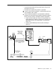
Figure S-11, below, shows a typical wiring installation for a MERLIN Plus
System. Local telephone lines connect with system wiring at a network
interface. Voice terminal wiring connects to the control unit through building
wiring and a jack field. Table
8-6
lists the material needed for the sample
configuration shown in Figure
8-11.
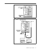
FIGURE 8-11 Typical MERLIN Pius system wiring installation.
I
I
102A Connecting
block with
65B
faceplate
I
I
Concealed wires
I
--___.
Surface
wiring
(5)
Control
unit
Illlli
ii
D6W cords
III
D2R
cords
D2R
cords
I I I I
I I
I I I
Z601A
adapters
I I
DIW
adapter
-line)
cable
Alternate
NI
arrangement
267C Adapter