
Specifications


ACCESSORY WIRING
3
Plug the labeled end of each intercom into the appropriately labeled jack
in the apparatus box of the jack field.
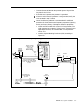
CO Line Wiring
See Figure 8-7 and follow these steps to install your telephone (CO) line
wiring:
1
Label each line cord running from the network interface to the control unit
(A through H).
2
Plug the unlabeled end of each line cord into the corresponding control
unit line jack.
3
Plug the labeled end of each line cord into the appropriately labeled jack
at the network interface.
FIGURE 8-7
installing CO line wiring.
Modular cord
to co
For future reference, you may want to make a copy of all the assignments
that are labeled at the jack field.
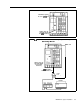
The following figures show the proper connections for MERLIN Plus
accessory features.
Figure 8-8 illustrates the wiring for Automatic System
Access features. Figure 8-9 shows how to wire Busy Buster and
the
data
collector when using the 450F adapter. Figure 8-10 shows the wiring for the
Music-on-Hold.
8-8 MERLIN Plus
System Installation