
Instruction manual

100DCD Module
4-3
100R INA and 100 DCD Modules
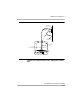
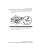
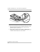
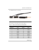
The 100 DCD data cable is shown below.
Figure 4-1. 100 DCD Data Cable
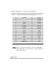
Pin assignments for the 25-pair cable are shown in Table 4-1
Table 4-1. Data Port 25-Pair Cable (P1) Pin Assignments
PIN Number Signal
PIN
Number
Signal
1 RD-A1 26 FRAME GND
2 RD-B1 27 RD-A2
3 TXC-A1 28 RD-B2
4 TXC-B1 29 TXC-A2
5 RXC-A1 30 TXC-B2
6 RXC-B1 31 RXC-A2
7 TD-A1 32 RXC-B2
8 TD-B1 33 TD-A2
9 DSR1 34 TD-B2