
Instruction manual

100DCD Module
4-2
Installation, SPM, Maintenance, and Troubleshooting Supplement
Therefore, it can be added to an existing MERLIN LEGEND Communications
System, where it functions like other 100 DS1 modules.
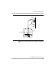
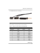
100 DCD Data Cable 4
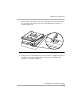
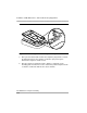
The 100 DCD module is connected to the customer’s equipment by use of a
cable consisting of a 50 position centronic pin (male) connector to a molded
V.35 socket (female) connector (port 1) and 25 position socket (female) d-sub
molded connector (port 2) that is supplied with each circuit module:
■ Data Port 1 provides a fixed V.35 interface terminated at an MS34 socket.
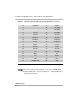
■ Data Port 2 terminates in an EIA-530-A interface via a DB25 socket. The
port supports multiple industry standard interfaces when used in
conjunction with standard adapter cables. RS-449, X.21 and V.35
interfaces are supported. Data Port 2 must be used when an interface
other than V.35 is required. It can also be used to provide a second V.35
interface. Nothing precludes using Data Port 2 in an application requiring a
single V.35 port so long as the proper cabling is provided.
Regardless of which port is used, the customer is responsible for providing the
cable that connects from ports 1 or 2 to the data endpoint.
■ You can install a 100 DCD into a MERLIN MAGIX Release 1.0 or a
MERLIN LEGEND system, but you need a MERLIN MAGIX system
of Release 1.5 or later to support the CSU/DSU functionality
■ The 100 DCD module firmware can be upgraded using a PCMCIA
card. If the 100 DCD module has no firmware installed, the System
Inventory Report shows “100 D/CSU/S No FW.”