
Instruction manual

The 4400-Series Telephone Family
3-10
Installation, SPM, Maintenance, and Troubleshooting Supplement
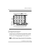
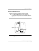
Follow these steps and refer to Figure 3-2 to connect one or two DSS 4450s:
1. Turn the telephone and each DSS 4450 face down.
2. Connect the one end of the D8Y line cord (supplied with the DSS 4450) to
the ADJ jack on the telephone. Connect the other end of the D8Y line cord
to the IN jack of the first DSS 4450 (next to the telephone).
3. If you are connecting only one DSS 4450, go to Step 4.
If you are connecting a second DSS 4450, connect one end of the D8Y line
cord (supplied with the DSS 4450) to the OUT jack of the first DSS 4450
connected in Step 2. Connect the other end of the D8Y line cord to the IN
jack on the second DSS 4450 (farthest from the telephone).
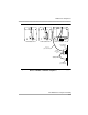
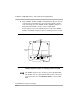
4. Connect one end of the satin-silver D4BU line cord (packaged with the
4424LD+ telephones) to the LINE jack of the telephone. Connect the other
end of the satin-silver D4BU line cord to the TEL jack of the Auxiliary Power
Supply Unit.
5. Connect one end of the clear D2R line cord (packaged with the 4400-
Series telephones and the DSS 4450) to the LINE jack of the Auxiliary
Power Supply Unit. Connect the other end of the clear D2R line cord to the
communications system wall jack.
6. Connect the Auxiliary Power Supply Unit to a 120 VAC wall outlet.
7. Turn the telephone and the DSS 4450s face up.
If the telephone does not work properly after all cords are
connected, check to be sure that the satin-silver D4BU line cord
and the clear D2R line cords are connected properly as shown
in Figure 3-2.