
Instruction manual

Installing the Cover on the Carrier
2-51
Installing the Control Unit
3. Turn on the power switch on the basic carrier power supply.
■ The dot on the one-character display LED flashes.
■ The green light on the power supply turns on.
■ The red light on the processor should turn on for 15 to 45 seconds and
then turn off.
■ All indicators on the 100 DS1, 100 DCD, 100R INA, and 400 E&M line/
trunk modules (if present) turn on and then off. They remain off when
the modules are idle.
4. If any of these conditions are not met, refer to Maintenance and
Troubleshooting.
Installing the Cover on the
Carrier
2
WARNING:
The cover must be installed for continued safe operation of the control
unit.
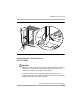
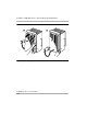
A front cover is needed for the carrier. Follow these steps to install the cover
(see Figure 2-15):
1. Be sure all wires have been passed through the wire managers and wire
trays at the bottom of the control unit.
2. Hook the top of the cover onto the top of the carrier.
3. Push in the bottom of the cover until it locks securely onto the base of the
wire managers on the carrier.
4. Tighten the two screws at the bottom of the cover.