
Instruction manual

Labeling
2-45
Installing the Control Unit
Labeling 2
After all modules have been installed, label the jacks by using the numbered
labels provided with the processor module. There are two types of labels:
■ Line/trunk labels have green numbers on off-white background.
■ Telephone labels have blue numbers on off-white background.
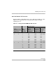
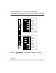
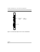
See Figure 2-13 on page 2-46 for the locations of line/trunk jacks and
telephone jacks on each module, and label them as described next.
Follow these steps to label the jacks on the modules:
1. Label each line/trunk jack on the modules sequentially, 1 through 80. Begin
with the module in slot 1, numbering from bottom to top on each module
and working from left to right across the carrier or carriers.
The 100 DS1, 100 DCD, and 100R INA modules each have 24 numbers
assigned to the line/trunk jack.
2. Label each telephone jack sequentially, 1 through 200. Begin with the
module in slot 1, numbering from bottom to top on each module and
working from left to right across the carrier or carriers.
CAUTION:
The 008 OPT module is assigned 12 logical IDs, and the last four
numbers are not assigned to jacks. For example, if the previous
module (on the left) is labeled with logical IDs 1 through 8, label the
008 OPT jacks with logical IDs 9 through 16. Skip numbers 17
through 20. When you label the next module (on the right), label the
first jack as logical ID 21.