
Instruction manual

Tie Trunks
2-41
Installing the Control Unit
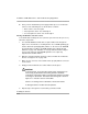
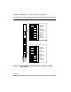
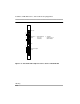
400 E&M Module DIP Switches 2
During installation of 400 E&M modules, refer to Table 2-6 and Table 2-7, and to
Figure 2-12 on page 2-44 for the correct DIP switch settings for varying
signaling protocols.
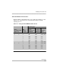
Table 2-6. Setting the 400 E&M Module DIP Switches
Signaling Type
Ports
(as numbered in
Figure 2-9)
DIP
Switch
Position
1S (Default)
and 1C
Unprotected
E&M Mode
1C and 1S
Protected
E&M Mode
5
Simplex
Mode
1 ON OFF OFF or ON
2 4 2 ON OFF OFF or ON
3 OFF OFF ON
4 OFF OFF ON
5 OFF OFF ON
6 ON OFF OFF or ON
1 3 7 ON OFF OFF or ON
8 OFF OFF ON
9 OFF OFF ON
10 OFF OFF ON