
Instruction manual

Tie Trunks
2-39
Installing the Control Unit
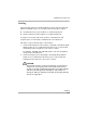
Installing the Cover 2
The cover is installed only after all equipment has been connected to the
control unit and after all system testing has occurred. The top edge of the front
cover hooks over the top flange of the carrier. The bottom of the front cover is
secured to the carrier with two captive screws.
WARNING:
The cover must be installed for continued safe operation of the control
unit.
Tie Trunks 2
Tie trunks connect two separate PBX communications systems either directly
or through one or more central offices, as if they were one system at the same
location. In the MERLIN MAGIX Integrated System, the 400 E&M module is the
originating and terminating unit for tie trunk operation.
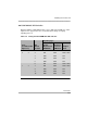
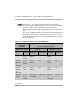
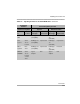
Tie Trunk Signaling 2
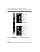
The 400 E&M (tie trunk) module can transmit signals in three different formats.
Each format is made up of a specific signaling mode and a specific signaling
type. The DIP switches on the 400 E&M module allow you to select the
signaling mode for tie trunk transmission. The signaling type is selected
through system programming.
The two captive screws should not be removed from the front
cover.