
Instruction manual

Installing the Carriers
2-38
Installation, SPM, Maintenance, and Troubleshooting Supplement
■ Once you have installed the power supply and the processor in the basic
carrier, use the remaining slots for the modules as follows:
— Basic carrier: slots 1 through 5
— First expansion carrier: slots 6 through 11
— Second expansion carrier: slots 12 through 17
Placing the Modules into the Carrier 2
To install modules starting from slot 1 (the first open slot next to the processor),
follow the steps below:
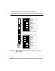
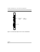
1. For each 400 E&M tie trunk module, for jacks numbered 1 through 4 in
Figure 2-12, check Form 3c, Incoming Trunks: Tie, for E&M signaling type.
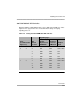
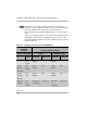
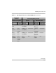
Set the dual in-line packaging (DIP) switches on the front of the 400 E&M
tie trunk module according to the E&M signaling type settings listed in
Table 2-6 on page 2-41 and Table 2-7 on page 2-42 and shown in Figure
2-12 on page 2-44. The default E&M signal does not require any
adjustments in the DIP switches.
2. Align the circuit board guides inside the carrier, and slide the module into
the slot. See Figure 2-11 on page 2-36.
3. Make sure the connector on the module mates properly with the connector
on the carrier.
4. Firmly push the module into the carrier until it locks into place.
CAUTION:
To avoid damage, do not force the module. If the module does not
insert easily, pry the bottom-front locking tab with a flat-blade
screwdriver, remove the module, and inspect the module and carrier
for damage or obstruction. The bottom-front locking tab is shown in
Figure 2-11. This tab is used on all modules.
If there is no damage and no obstruction, reinsert the module.
A damaged carrier or module must be replaced.
5. Repeat Steps 1 through 4 for each module you want to install.