
Instruction manual

Installing the Carriers
2-31
Installing the Control Unit
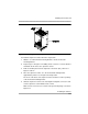
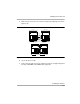
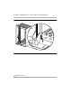
5. Make sure the connectors are seated securely and completely as shown in
Figure 2-10.
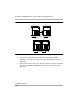
Figure 2-10. Connecting the Carriers
6. Secure the three screws.
7. Connect the ground-screw on the expansion carrier to an approved ground
by using a #12 AWG or #14 AWG solid copper wire.
Basic Carrier
Expansion Carrier
Basic Carrier
Expansion Carrier
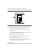
Backboard
Connector
Carrier
Extender
(under the
breakaway tab)