
Instruction manual

100DCD Module
4-9
100R INA and 100 DCD Modules
DIP Switches 4
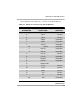
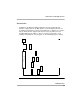
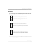
In addition to the different cabling required for the various physical level
interfaces supported there are DIP switches on the module that must be set
according to what interface is being used. Data Port 1’s switches are set at the
factory and are fixed to support V.35 only, hence they should never need
changing. Data Port 2’s switches can be set in either of two modes, V.35
(default) or RS-449/X.21. See the figures on the following pages for settings.
Figure 4-2. 100 DCD Data Port DIP Switch Placement
TelCo
Connector
S
1
7
0
2
S
1
7
0
1
S
1
7
0
0
S
1
7
0
3
S
1
2
0
2
S
1
2
0
1
S
1
2
0
0
S
1
2
0
3
Mod
Jack