
Instruction manual

100DCD Module
4-7
100R INA and 100 DCD Modules
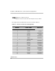
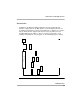
Data Port Interface signal descriptions are shown in Table 4-3.
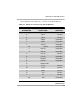
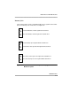
17 RXC-A2 FROM DSU
18 LL2 TO DSU
19 RTS-B2 TO DSU
20 DTR2 TO DSU
21 RL2 TO DSU
22
23
24 TT-A2 TO DSU
25 TM2 FROM DSU
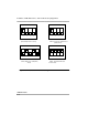
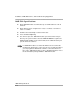
■ V.35, RS449 and X.21 interfaces require an adapter cable.
■ DB25S connector is at the end of the 25-pair connector cable A.
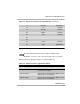
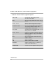
Table 4-4. Data Port Interface Signal Descriptions
Signal Description
RD-A, RD-B Receive Data, differential pair, data
transmitted to the DTE.
TXC-A, TXC-B Transmit Clock, differential pair, DCE sourced
timing reference for TD-A/B.
RXC-A, RXC-B Receive Clock, differential pair, DCE sourced
timing reference for RD-A/B.
Table 4-3. Data Port 2 Connector Pin Assignments—Continued