
Instruction manual

100DCD Module
4-6
Installation, SPM, Maintenance, and Troubleshooting Supplement
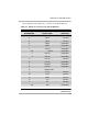
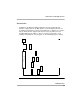
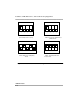
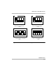
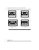
Pin assignments for the Data Port 2connector are shown in Table 4-3.
■ Data Port 1 supports V.35 only.
■ MS34 connector is at the end of the 25-pair connector cable B.
Table 4-3. Data Port 2 Connector Pin Assignments
CABLE DB25S PIN
NUMBER
CONNECTOR
SIGNAL NAME
DIRECTION
1 FRAME GND
2 TD-A2 TO DSU
3 RD-A2 FROM DSU
4 RTS-A2 TO DSU
5 CTS-A2 FROM DSU
6 DSR2 FROM DSU
7 SIGNAL GND
8 RLSD-A2 FROM DSU
9 RXC-B2 FROM DSU
10 RLSD-B2 FROM DSU
11 TT-B2 TO DSU
12 TXC-B2 FROM DSU
13 CTS-B2 FROM DSU
14 TD-B2 TO DSU
15 TXC-A2 FROM DSU
16 RD-B2 FROM DSU