
Instruction manual

100DCD Module
4-4
Installation, SPM, Maintenance, and Troubleshooting Supplement
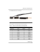
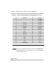
10 SIG-GND 35 DSR2
11 36 SIG-GND
12 37 SIG-GND
13 CTS-A1 38 SIG-GND
14 CTS-B1 39 CTS-A2
15 RLSD-A1 40 CTS-B2
16 RLSD-B1 41 RLSD-A2
17 TT-A1 42 RLSD-B2
18 TT-B1 43 TT-A2
19 RTS-A1 44 TT-B2
20 RTS-B1 45 RTS-A2
21 LL1 46 RTS-B2
22 DTR1 47 LL2
23 RL1 48 DTR2
24 TM1 49 RL2
25 FRAME GND 50 TM2
■ Connector shell pins G1 and G2 are connected to FRAME GND.
■ Signals qualified by a 1 belong to Data Port 1, signals qualified by a
2 belong to Data Port 2.
Table 4-1. Data Port 25-Pair Cable (P1) Pin Assignments—Continued