Lucent Technologies Bell Labs Innovations MERLIN MAGIX™ Integrated System Release 1.0/1.
Copyright and Legal Notices Copyright © 2000, Lucent Technologies All Rights Reserved Printed in USA Document 555-710-142 Comcode 108522343 Issue 1 June 2000 Notice Every effort has been made to ensure that the information in this guide is complete and accurate at the time of printing. Information, however, is subject to change. See Appendix A, “Customer Support Information,” in Feature Reference for important information.
Copyright and Legal Notices appareils numériques de la classe A préscrites dans le réglement sur le brouillage radioélectrique édicté par le ministère des Communications du Canada. Year 2000 Compliance The MERLIN MAGIX Integrated System is certified to be Year 2000 compliant. Additional information on this certification, and other issues regarding Year 2000 compliance, is available online at http://www.lucent.com/enterprise/sig/yr2000.
Copyright and Legal Notices Support Telephone Number In the continental US, Lucent Technologies provides a toll free customer helpline 24 hours a day. Call the Lucent Technologies Helpline at 1 800 628-2888 or your Lucent Technologies authorized dealer if you need assistance when installing, programming, or using your system. Outside the continental US, contact your local Lucent Technologies authorized representative.
IMPORTANT SAFETY INSTRUCTIONS The exclamation point in an equilateral triangle is intended to alert the user to the presence of important operating and maintenance (servicing) instructions in the literature accompanying the product. To reduce the risk of fire, electrical shock, and injury to persons, follow these basic safety precautions when installing telephone equipment: ■ Read and understand all instructions. ■ Follow all warnings and instructions marked on or packed with the product.
Installation, SPM, Maintenance, and Troubleshooting Supplement ■ The MERLIN MAGIX Integrated System is equipped with a 3-wire groundingtype plug with a third (grounding) pin. This plug will fit only into a groundingtype power outlet. This is a safety feature. If you are unable to insert the plug into the outlet, contact an electrician to replace the obsolete outlet. Do not defeat the safety purpose of the grounding plug. ■ The MERLIN MAGIX Integrated System requires a supplementary ground.
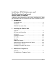
Installation, SPM, Maintenance, and Troubleshooting Supplement Master Table of Contents 1 Introduction The Control Unit. . . . . . . . . . . . . . . . . . . . . . . . . . . . . . . . . . . 1-1 Telephones . . . . . . . . . . . . . . . . . . . . . . . . . . . . . . . . . . . . . 1-10 PCMCIA Translation Card . . . . . . . . . . . . . . . . . . . . . . . . . . 1-11 2 Installing the Control Unit Overview . . . . . . . . . . . . . . . . . . . . . . . . . . . . . . . . . . . . . . . .
Installation, SPM, Maintenance, and Troubleshooting Supplement 4 100R INA and 100 DCD Modules Overview . . . . . . . . . . . . . . . . . . . . . . . . . . . . . . . . . . . . . . . . 4-1 100DCD Module . . . . . . . . . . . . . . . . . . . . . . . . . . . . . . . . . . 4-1 100R INA Specifications . . . . . . . . . . . . . . . . . . . . . . . . . . . 4-14 New Programming Options . . . . . . . . . . . . . . . . . . . . . . . . . 4-15 100R INA/100 DCD System Conditions . . . . . . . . . . . . . . .
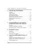
Master Table of Contents 8 System Programming Maintenance Overview . . . . . . . . . . . . . . . . . . . . . . . . . . . . . . . . . . . . . . . . 8-1 System Requirements . . . . . . . . . . . . . . . . . . . . . . . . . . . . . . 8-2 Installing the WinSPM Software. . . . . . . . . . . . . . . . . . . . . . . 8-4 Getting Started. . . . . . . . . . . . . . . . . . . . . . . . . . . . . . . . . . . . 8-5 WinSPM Main Screen . . . . . . . . . . . . . . . . . . . . . . . . . . . . . 8-23 Using Quick Access . .
Introduction 1 1 The MERLIN MAGIX system has been developed for the medium-size business market. Electronically, it is very similar to a MERLIN LEGEND Communications System. However, new modules and new telephones have been developed to work with the MERLIN MAGIX system. The Control Unit 1 The control unit of the MERLIN MAGIX system consists of a basic carrier and, optionally, one or two expansion carriers.
Installation, SPM, Maintenance, and Troubleshooting Supplement Power Supply 1 CAUTION: Grounding circuit continuity is vital for safe operation of the MERLIN MAGIX system. Never operate with the grounding conductor disconnected. The ground-screw connection is located on the carrier. The 491D1 (100–240 V AC) power supply modules can provide up to 96 unit loads of current per carrier; therefore, an auxiliary power unit is not required with these modules.
Introduction Station Module Specifications 1 491D1 Power Supply Module: ■ Power Input: 100–240 V AC, 5A, 50/60 Hz ■ Power Output: +5.1 V DC ±5% (10A), –5.1 V DC ±5% (1.5A), –48 V DC ±10% (3.
Installation, SPM, Maintenance, and Troubleshooting Supplement 100 DCD Module 1 The 100 DCD module functions like the 100 DS1 module but has a built-in channel service unit (CSU) and data service unit (DSU). Therefore, this module needs no external CSU or DSU. The module accommodates up to 23 PRI channels and 24 T1 channels. The CSU/DSU functionality of the 100 DCD module is supported only in MERLIN MAGIX systems of Release 1.5 or later. The 100 DCD module can fit into both metal and plastic carriers.
Introduction Only a 4424D+ or 4424LD+ telephone can be connected to an eligible operator position port assigned as a Direct-Line Console (DLC) operator position; only a 4424LD+ telephone can be connected to an eligible operator position port assigned as a Queued Call Console (QCC) operator position.
Installation, SPM, Maintenance, and Troubleshooting Supplement MERLIN LEGEND Modules Supported by the Metal Carrier 1 Modules introduced in releases of the MERLIN LEGEND Communications System are available in a version without the plastic shell and can be inserted into the metal carrier of a MERLIN MAGIX system.
Introduction MERLIN LEGEND Modules Supported for Upgrade 1 The MERLIN MAGIX system software also supports modules from the MERLIN LEGEND Communications System that cannot fit into the metal carrier of the MERLIN MAGIX system. However, they can be used when you upgrade a MERLIN LEGEND system to a MERLIN MAGIX system. (See “Upgrading to the MERLIN MAGIX System” on page 7-9 for more details.
Installation, SPM, Maintenance, and Troubleshooting Supplement Table 1-1 lists all the modules supported by the MERLIN MAGIX software. Table 1-1.
Introduction Table 1-1.
Installation, SPM, Maintenance, and Troubleshooting Supplement MERLIN LEGEND Modules Not Supported 1 The following modules are not supported by the MERLIN MAGIX system software and must be removed from the plastic carrier before upgrading: ■ 008 (ATL) ■ 400 LS/TTR ■ 408 LS (ATL) ■ 408 GS/LS (ATL) Telephones 1 The MERLIN MAGIX system supports the following telephones: ■ 4400-Series ■ MLX ■ ETR ■ MLS ■ Single-line ■ TransTalk® MDW 9031 The MERLIN MAGIX system does not support analog mu
Introduction PCMCIA Translation Card 1 The 2MB translation card (10A2) is used to maintain “Back-Up” System translations for the MERLIN MAGIX system. The procedures for using a 2MB translation card are the same as those for the 4MB card used with the MERLIN LEGEND Communications System. Upgrade Card 1 Beginning in Release 1.5 of the MERLIN MAGIX system, an Upgrade PCMCIA card is available to upgrade the system software to MERLIN MAGIX Release 1.
Installation, SPM, Maintenance, and Troubleshooting Supplement PCMCIA Translation Card 1-12
Installing the Control Unit 2 2 If you have not read Chapter 1, “Introduction,” do so before continuing with this chapter.
Installation, SPM, Maintenance, and Troubleshooting Supplement Environment 2 The control unit must be installed on a backboard. The placement of the backboard, and the control unit on it, requires careful consideration. Make sure you install the backboard in an area that meets all of the environmental requirements listed in Table 2-1. Table 2-1. Environmental Requirements Parameter Value Operating Temperatures 40ο–104οF (4ο–40οC) Optimal temperature: 60οF (15.
Installing the Control Unit WARNING: Do not install the control unit outdoors. Electrical Noise/Radio-Frequency Interference 2 In most cases, electrical noise is introduced into the system through trunk or telephone cables. However, electromagnetic fields near the control unit can also cause noise in the system. Therefore, you should not place the control unit and cable runs in areas where a high electromagnetic field strength exists.
Installation, SPM, Maintenance, and Troubleshooting Supplement Control Unit Dimensions and Location 2 The following are the dimensions and location requirements for the control unit: ■ Dimensions — Basic carrier: 11 inches wide by 20 inches high by 11 inches deep — Basic carrier and one expansion carrier: 22 inches wide by 20 inches high by 11 inches deep — Basic carrier and two expansion carriers: 33 inches wide by 20 inches high by 11 inches deep ■ Location — Within 5 feet (152 cm) of an AC power ou
Installing the Control Unit Backboard Requirements 2 The backboard should be wide enough to accommodate the carrier and up to two additional carriers, assuming that system growth is anticipated. There should be enough room on each side of the control unit for the necessary wiring fields.
Installation, SPM, Maintenance, and Troubleshooting Supplement Installing the Backboard 2 When you are certain that the backboard meets the requirements indicated above. Use the following mounting hardware: ■ For a wood mounting surface, use wood screws. ■ For brick, cinderblock, or concrete, use masonry anchors. ■ For plaster or plasterboard, use toggle bolts. ■ For sheet metal, use sheet-metal screws and attach them to the structural members.
Installing the Control Unit ■ All AC outlets must connect to the same load center and the ground wire must connect to the single-point ground bar on the first AC outlet (see Figure 2-1). ■ One outlet must have an attached ground bar connected by a #6 AWG copper wire to an approved ground (see “Approved Grounds” later in this chapter, for a description of approved grounds). This ground bar is the system’s single-point ground (see Figure 2-1).
Installation, SPM, Maintenance, and Troubleshooting Supplement From AC Load Center (2 separately fused 15 A circuits) Ground Wire #14 AWG 4" Box (RACO 230 or equivalent) HUBBELL Receptacles (5262 15 A or equivalent) 4" Cover (RACO 807 or equivalent) Single-Point Ground Ground Bar Mounted on a 4" Box (Square "D" PK9GTA or approved equivalent) Ground Wire #6 AWG Copper Approved Building Ground #12 or #14 AWG Copper Wire to Each Carrier Grounding Screw Figure 2-1.
Installing the Control Unit AC Outlet Tests 2 If the AC outlet tests indicate that any of the power requirements in Table 2-2 are not met, your customer must contact a licensed electrician. Do not install the system until all requirements are met. Table 2-2.
Installation, SPM, Maintenance, and Troubleshooting Supplement Using an Ideal 61-035 Circuit Tester (or Equivalent) 2 Follow these steps to use an Ideal 61-035 Circuit Tester or its equivalent: 1. Plug the circuit tester into the outlet that you want to test. If the circuit is properly grounded, the yellow and white lights on the tester turn on. 2. Unplug the circuit tester. Using a Volt-Ohm Milliammeter (VOM) 2 Follow these steps to use a VOM: 1.
Installing the Control Unit 110 - 125 Volts AC Phase (HOT) Neutral Ground Less than 1.0 Volt AC 110 - 125 Volts AC Figure 2-2. Measuring the AC Outlet Voltages WARNING: If the voltage readings do not measure the values required, the AC outlet is improperly wired—do not install the system. Advise the customer to have a licensed electrician correct the problem.
Installation, SPM, Maintenance, and Troubleshooting Supplement WARNING: When installing the control unit, make sure you meet the following grounding requirements: ■ The control unit, the central office trunk protector, and the AC power service panel should be as close to each other as possible.
Installing the Control Unit To Central Office or Serving Facility CO Lines CO Line Protector Network Interface DIW or 25-Pair Cable CO Wiring Field Coupled Bonding Conductor (optional) D2R Cords Power ) (Supply Commercial Power Ground Screw Connection AC Plug Outlet #12 or #14 AWG Ground Wire #6 AWG Ground Wire Earth Ground Bond Wire Single Point Ground Bar B W Power Service GND (Green) Shield Ground Power Ground Rod Figure 2-3.
Installation, SPM, Maintenance, and Troubleshooting Supplement WARNING: An improper ground can cause equipment failures, service outages, and electrical shock. Verify that the AC power uses an approved ground for its primary ground, that all voltage-limiting devices are grounded to an approved ground, and that the ground is one of the approved grounds listed below.
Installing the Control Unit — 20 feet (6.1 m) of bare copper conductor not smaller than #4 AWG, encased in 2 inches (5 cm) of concrete This electrode must be located within and near the bottom of a concrete foundation or footing that is in direct contact with the earth. — Ground ring, consisting of at least 20 feet (6.1 m) of bare copper conductor (not smaller than #2 AWG) encircling the building.
Installation, SPM, Maintenance, and Troubleshooting Supplement Heavy Lightning Protection 2 The MERLIN MAGIX 491D1 power supply has built-in AC line protection. This built-in protection handles almost all situations. Occasionally, additional protection may be needed if the customer is located in a heavy lightning area. In such instances, the 145D and 146 protectors are available for the MERLIN MAGIX system as needed.
Installing the Control Unit Table 2-3. Capacities and Recommended Application for 146 Protectors—Continued Protector Recommended Application 146E 2 MLX IROB telephones 2 4400-Series IROB telephones 146F 25 CO Lines 25 T/R IROB telephones 145D 6 protected AC outlets For detailed installation instructions, see the documentation packaged with the protectors.
Installation, SPM, Maintenance, and Troubleshooting Supplement 145D Protector 146C Protector A LW AY S O N Status Indicator Lights KSU GROUND 1 POWER PROTECTION PROTECTOR FOR 4 TIP/RING LINES 2 3 4 GROUND OK CO LINES Ground Strap 1 2 146C CO/4x4 PROTECTOR SECONDARY TELEPHONE PROTECTOR LISTED 32Y1 E141535 LR58861 3 4 KSU PORTS L I N E F A U LT AC Connection 145D 6-AC SURGE PROTECTOR TRANSIENT VOLTAGE SURGE SUPPRESSOR To Central Office or IROB LISTED 2J51 E99768 LR58861 To Control Unit
Installing the Control Unit Unit Loads 2 A unit load is a measure of power (1.9 watts) that you use to determine the electrical load that the components listed below place on the control unit’s power supply. ■ Telephones and adjuncts ■ 800 DID modules Only the telephones and adjuncts that connect to the digital extension jacks (ports) on the control unit require unit load calculation. When calculating unit load, do not include any equipment with its own power supply (for example DSS).
Installation, SPM, Maintenance, and Troubleshooting Supplement Calculating Unit Loads 2 The 491D1 power supply for the MERLIN MAGIX Integrated System provides up to 96 unit loads of power. If the unit loads in a carrier exceed 96 unit loads, reconfigure the carrier so that the unit loads are 96 or less.
Installing the Control Unit Table 2-4. Unit Loads Per Module (48vDC)—Continued Circuit Module App Code Type UNIT LOAD 617A54 016 MLX 27 617E34 016 T/R 12.8 617A56 016 ETR 24 617B35 800 NI-BRI 0 617G20 800 DID 8.0 617 E28 008 OPT 8.0 617D14 400 E&M 8.0 617B31 800 GS/LS-ID 0 617N15 100 DS1 0 617S15 100 DCD 0 617E29 408GS/LS-ID-MLX 13.5 617A49 MERLIN Messaging 0 2.
Installation, SPM, Maintenance, and Troubleshooting Supplement Table 2-5. Unit Loads Per Port Port Load Hybrid/PBX Mode Square-Key Mode 4424LD+ 1.1 1.3 4412D+/4424D+ 1.1 1.3 4400/4400D/4406D+ 0.9 1.0 DSS 0 0 MLX-20L 1.1 1.6 MLX-28 1.2 1.7 MLX 5/10/16 w/ or w/o Disp 0.9 1.2 DSS 0.7 0.9 MFM (use local PSU) 0 0 0.6 0.7 ETR-6 0.9 1.0 ETR-18 1.0 1.2 ETR-18D 1.2 1.4 ETR-34D 1.5 1.
Installing the Control Unit Table 2-5. Unit Loads Per Port—Continued Port Load Hybrid/PBX Mode Square-Key Mode GS-LS 0 0 DID 1.0 1.0 E&M 1.4 1.4 DS1 0 0 Trunk If the total exceeds the maximum unit loads per power supply, try to exchange modules between carriers to reduce the load below the maximum. No empty slots are permitted between modules.
Installation, SPM, Maintenance, and Troubleshooting Supplement Installing the Carriers 2 Installation of the basic and expansion carriers involves mounting the carriers to the backboard, connecting the ground, placing the power supply, processor, and modules into the carriers, and attaching the front cover.
Installing the Control Unit To install the basic carrier, follow the steps below: 1. Install the horizontal mounting bracket on the backboard using at least two #10 X 3/4” long wood screws supplied. Make sure that the bracket is level. 2. Install the top of the vertical mounting bracket into the slot on the horizontal mounting bracket to form a “T,” as shown in Figure 2-5. Secure the vertical mounting bracket with at least one #10 X 3/4” long wood screw in the bottom hole. Figure 2-5.
Installation, SPM, Maintenance, and Troubleshooting Supplement Figure 2-6. Fastening the left and right brackets on the carrier 4. Place the carrier on to the horizontal mounting bracket approximately 2 inches to the right of its final position. The hook on the back of the carrier should rest on the top flange of the horizontal mounting bracket. 5. Slide the carrier to the left until it stops when it bottoms out on the vertical mounting bracket.
Installing the Control Unit Figure 2-7. Securing the left and right bracket To Install the expansion carrier, follow the steps below: 1. Abut the second horizontal mounting bracket to the first horizontal mounting bracket. 2. Repeat steps 1 through 3 for installing a basic carrier to secure the bracket and attach the mounts to the expansion carrier. 3. Remove the filler plate from the right side of the basic (first) carrier. See Figure 2-7 above. 4.
Installation, SPM, Maintenance, and Troubleshooting Supplement Basic Carrier Expansion Carrier Connector Carrier Extender (under the breakaway tab) Backboard Basic Carrier Expansion Carrier Figure 2-8. Connecting the Carriers 6. Secure the left and right mounting brackets to the backboard with a minimum of one 10 X 3/4” long wood screw in each bracket as shown in Figure 2-7. 7. Connect the ground-screw on the expansion carrier to an approved ground by using a #12 AWG or #14 AWG solid copper wire.
Installing the Control Unit Mounting the Carriers With the Power Supply and Port Modules Removed 2 This installation procedure does not require the 4 mounting brackets supplied with each carrier. A basic carrier should be mounted on a backboard with 29 inches (73.66 cm) of empty space to the right. This allows enough room for system expansion of two additional carriers.
Installation, SPM, Maintenance, and Troubleshooting Supplement Mounting Surface Mounting Screw Backboard Basic Carrier Figure 2-9. Marking the Basic Carrier Screw Holes 2. Drill a pilot hole in the center of each of the three screw-hole marks. 3. Anchor the screws approximately halfway into the backboard. 4. Position the basic carrier on the screws and slide the carrier to the left. 5. Tighten the screws. 6.
Installing the Control Unit 5. Make sure the connectors are seated securely and completely as shown in Figure 2-10. Basic Carrier Expansion Carrier Connector Carrier Extender (under the breakaway tab) Backboard Basic Carrier Expansion Carrier Figure 2-10. Connecting the Carriers 6. Secure the three screws. 7. Connect the ground-screw on the expansion carrier to an approved ground by using a #12 AWG or #14 AWG solid copper wire.
Installation, SPM, Maintenance, and Troubleshooting Supplement Installing the Power Supply 2 WARNING: Do not install the power supply unless the carrier is connected to an approved ground. Before touching leads, connectors, pins, and other components, use a properly grounded wrist strap, to prevent damage from electrostatic discharge (ESD). The wrist strap can be clipped to the ground screw or plugged into the hole next to the ground screw.
Installing the Control Unit Installing the Processor 2 CAUTION: Before touching leads, connectors, pins, and other components when handling the circuit board, use a properly grounded wrist strap to prevent damage from electrostatic discharge (ESD). The wrist strap can be clipped to the ground-screw or plugged into the hole next to the groundscrew.
Installation, SPM, Maintenance, and Troubleshooting Supplement If the system is programmed for Permanent Key mode, check the switch setting. Refer to “Modifying the Processor for Key Mode” in Chapter 9 for detailed procedures. If the switch is set to Permanent Key-only operation, all trunks revert to loop-start. If the switch is not set, any programmed designation for ground-start trunks is retained.
Installing the Control Unit CAUTION: To avoid damage, do not force the module. If the module does not insert easily, pry the bottom-front locking tab with a flat-blade screwdriver, remove the module, and inspect the module and carrier for damage or obstruction. The bottom-front locking tab is shown in Figure 2-11. This tab is used on all modules. If there is no damage and no obstruction, reinsert the module. A damaged carrier or module must be replaced. 3.
Installation, SPM, Maintenance, and Troubleshooting Supplement Figure 2-11.
Installing the Control Unit Installing the Modules 2 CAUTION: When installing the modules, use a properly grounded wrist strap to prevent damage from electrostatic discharge (ESD), and avoid touching leads, connectors, pins, and other components. The wrist strap can be clipped to the ground-screw or plugged into the hole next to the groundscrew. WARNING: All unused slots must be covered with a blank panel. Remove back panels only from slots where modules will be installed.
Installation, SPM, Maintenance, and Troubleshooting Supplement ■ Once you have installed the power supply and the processor in the basic carrier, use the remaining slots for the modules as follows: — Basic carrier: slots 1 through 5 — First expansion carrier: slots 6 through 11 — Second expansion carrier: slots 12 through 17 Placing the Modules into the Carrier 2 To install modules starting from slot 1 (the first open slot next to the processor), follow the steps below: 1.
Installing the Control Unit Installing the Cover 2 The cover is installed only after all equipment has been connected to the control unit and after all system testing has occurred. The top edge of the front cover hooks over the top flange of the carrier. The bottom of the front cover is secured to the carrier with two captive screws. The two captive screws should not be removed from the front cover. WARNING: The cover must be installed for continued safe operation of the control unit.
Installation, SPM, Maintenance, and Troubleshooting Supplement Signaling Modes 2 There are two signaling modes: ■ E&M. This is a standard interface. The E&M signaling leads are separate from the transmission leads, requiring a 3-pair wire interface. ■ Simplex. In Simplex, the two signaling leads are superimposed onto the analog transmission leads, providing a 2-pair wire interface for connecting two local systems at minimal cost.
Installing the Control Unit 400 E&M Module DIP Switches 2 During installation of 400 E&M modules, refer to Table 2-6 and Table 2-7, and to Figure 2-12 on page 2-44 for the correct DIP switch settings for varying signaling protocols. Table 2-6.
Installation, SPM, Maintenance, and Troubleshooting Supplement DIP switches 1, 2, 6, and 7 determine whether the tie trunks are protected or unprotected. DIP switches 3, 4, 5, 8, 9, and 10 determine the mode. Simplex mode is always protected. Therefore the Protected/Unprotected settings for DIP switches 1, 2, 6, and 7 have no effect. The successful implementation of a tie trunk format is dependent upon matching the characteristics of both PBX systems it connects.
Installing the Control Unit Table 2-7.
Installation, SPM, Maintenance, and Troubleshooting Supplement O N 1 2 3 4 5 6 7 8 9 10 4 3 Switches 1 through 5 control Port 4 (1C. E&M unprotected) Switches 6 through 10 control Port 3 (1C. E&M protected) O N 1 2 3 4 5 6 7 8 9 10 2 1 Switches 1 through 5 control Port 2 (5 simplex) Switches 6 through 10 control Port1 (1C. E&M protected) Figure 2-12.
Installing the Control Unit Labeling 2 After all modules have been installed, label the jacks by using the numbered labels provided with the processor module. There are two types of labels: ■ Line/trunk labels have green numbers on off-white background. ■ Telephone labels have blue numbers on off-white background. See Figure 2-13 on page 2-46 for the locations of line/trunk jacks and telephone jacks on each module, and label them as described next.
Installation, SPM, Maintenance, and Troubleshooting Supplement PFT Jack 8 5 4 Line/Trunk or ExtensionTelephone Jacks Jacks on all 016 Modules or Off-Premise Telephone Jacks on 008 OPT Module 1 PFT 8 Extension Telephone Jacks 1 Figure 2-13.
Installing the Control Unit Replacing a Module 2 CAUTION: This section does not apply to the processor or power supply modules. Before inserting or removing a module, the power switch on all power supplies must be turned off. When you replace a module, use the same module type. For example, do not put a 008 MLX module in place of a 400 E&M module.
Installation, SPM, Maintenance, and Troubleshooting Supplement CAUTION: Follow these steps in the exact sequence. a. Turn off the power supply on the basic carrier. b. Turn off the power supplies on the expansion carriers. c. Unplug the system from the AC outlet. 3. Remove the module from the carrier. Follow these steps: a. Using a screwdriver, pry the tab at the bottom front of the module. b. While prying the tab, pull the top handle on the module towards you and away from the carrier. 4.
Installing the Control Unit Figure 2-14. Removing a Module from the Carrier Connecting the Control Unit to an AC Outlet 2 CAUTION: Make sure the AC outlet has been tested for proper grounding. The outlet should be 117 V AC, 60 Hz, 3-wire (phase, neutral, ground). See “AC Outlet Tests,” earlier in this chapter, for instructions. To prevent someone from accidentally shutting off the power, do not connect the control unit to a switch-controlled outlet.
Installation, SPM, Maintenance, and Troubleshooting Supplement To connect the control unit to a dedicated AC outlet, follow the steps below. 1. Turn the basic carrier’s power supply switch to the OFF position. 2. Turn off the power supply switches on the expansion carriers. 3. Plug one end of the power cord into the AC INPUT connector located to the right of the power switch on the front of the basic carrier’s power supply. 4.
Installing the Control Unit 3. Turn on the power switch on the basic carrier power supply. ■ The dot on the one-character display LED flashes. ■ The green light on the power supply turns on. ■ The red light on the processor should turn on for 15 to 45 seconds and then turn off. ■ All indicators on the 100 DS1, 100 DCD, 100R INA, and 400 E&M line/ trunk modules (if present) turn on and then off. They remain off when the modules are idle. 4.
Installation, SPM, Maintenance, and Troubleshooting Supplement Figure 2-15.
4400-Series Telephones Overview 3 3 3 The 4400-Series digital single-line and multiline telephones are designed for use with Lucent Technologies’ MERLIN MAGIX™ Integrated System. The 4400-Series includes display and non-display telephones and a 24-button model that can serve as the system programming console. Most of the instructions for the use of these telephones appear in the 4400 and 4400D Telephone User’s Guide and the 4406D+, 4412D+, 4424D+, and 4424LD+ Telephone User’s Guide.
Installation, SPM, Maintenance, and Troubleshooting Supplement Overview 3-2 ■ Never install a telephone jack in a wet location unless the jack is specifically designed for wet locations. ■ Never touch uninsulated telephone wires or terminals unless the telephone wiring has been disconnected at the network interface. ■ Use caution when installing or modifying telephone lines.
4400-Series Telephones The 4400-Series Telephone Family 3 The 4400-Series consists of the following models: ■ 4400 ■ 4400D ■ 4406D+ ■ 4412D+ ■ 4424D+ ■ 4424LD+ The “+” sign after a model indicates that the telephone has a speakerphone. The “D” indicates a two-line display, while “LD” stands for “large display,” the seven-line display. All telephones are two-wire digital telephones.
Installation, SPM, Maintenance, and Troubleshooting Supplement 4400D 3 The 4400D model is a single-line telephone with a display. It operates like an analog single-line telephone but has a display that shows feedback messages. The 4400D telephone has the following fixed buttons: ■ Volume ■ Hold ■ Conf (Conference) ■ Trnsfr (Transfer) ■ Redial 4406D+ 3 The 4406D+ telephone has six line buttons and a speakerphone. A two-line display provides feedback for features, including messages.
4400-Series Telephones 4412D+ 3 The 4412D+ telephone contains 24 line buttons, but only 12 of these have LEDs associated with them. You can use the two-line display to choose features; the display’s functionality is much like that of an MLX-28D telephone. The 4412D+ telephone also has a speakerphone.
Installation, SPM, Maintenance, and Troubleshooting Supplement 4424D+ 3 All 24 line buttons on the 4424D+ telephone have associated LEDs. You can use the four softkeys to choose options from the two-line display in the same way you choose options with the MLX-28D telephone.
4400-Series Telephones 4424LD+ 3 The 4424LD+ telephone has a seven-line display with eleven softkeys and 24 line buttons. Each line button has an associated pair of LEDs. Because of the larger display, you must use the external power supply that comes with the 4424LD+ telephone.
Installation, SPM, Maintenance, and Troubleshooting Supplement DSS 4450 3 One or two Direct Station Selector (DSS) 4450s can be connected to a 4424LD+ or 4424D+ telephone to enhance the call-handling capabilities of a system operator with a Direct-Line Console (DLC) or a Queued Call Console (QCC). When connected to a 4424LD+ telephone used as a system programming console, the DSS 4450 facilitates system programming and centralized telephone programming procedures.
4400-Series Telephones DSS4450 LEDs (50) Line Buttons (50) Page Buttons Reserved Buttons Message Status Button Figure 3-1. DSS4450 Connecting the DSS 4450 and Auxiliary 3 Power Supply Unit to the Telephone You may connect up to two Direct Station Selector (DSS) 4450s to a 4424LD+ or 4424D+ telephone. Use the “ADJ” jack on the bottom of the telephone for this purpose. The 4412D+ also has a jack marked “ADJ”; however, the jack is reserved for future use and cannot be used to connect a DSS 4450.
Installation, SPM, Maintenance, and Troubleshooting Supplement Follow these steps and refer to Figure 3-2 to connect one or two DSS 4450s: 1. Turn the telephone and each DSS 4450 face down. 2. Connect the one end of the D8Y line cord (supplied with the DSS 4450) to the ADJ jack on the telephone. Connect the other end of the D8Y line cord to the IN jack of the first DSS 4450 (next to the telephone). 3. If you are connecting only one DSS 4450, go to Step 4.
4400-Series Telephones OUT IN OUT IN LINE 2nd DSS 1st DSS ADJ Telephone Grounding Type Power Outlet LINE Auxiliary Power Supply Unit TEL Line Cord (Satin Silver D4BU) Line Cord (D2R) Communications System Wall Jack Figure 3-2.
Installation, SPM, Maintenance, and Troubleshooting Supplement Line Cords 3 Line cords are shipped with all 4400-Series telephones and the DSS 4450. The line cord varies according to the equipment: ■ Clear 14 foot, 6-position line cord with two conductors (D2R)—used to connect the 4400, 4400D, 4406D+, 4412D+, and 4424D+ telephones to the communications system wall jack. If auxiliary power is needed, use this cord to connect the Auxiliary Power Supply Unit to the communications system wall jack.
4400-Series Telephones Jacks and the Placement of Cords 3 Jacks exist on the bottom of the 4400-Series telephones as follows: ■ On the 4400 and 4400D telephones the jacks on the bottom accommodate the connection of the handset and the line cord. Refer to Figure 3-3 for jacks and placement of cords for the 4400 and 4400D telephones. Line Cord (D2R) LINE Handset Cord Figure 3-3.
Installation, SPM, Maintenance, and Troubleshooting Supplement ■ On the 4406D+, 4412D+, 4424D+, and 4424LD+ telephones the jacks on the bottom accommodate the connection of the handset, the line cord, and a headset. For the 4424D+ and the 4424LD+ telephone, a wider jack marked “ADJ” is used to connect a DSS 4450. Refer to Figure 3-4 for jacks and placement of cords for the 4406D+, 4412D+, and 4424D+ telephones when no auxiliary power is needed.
4400-Series Telephones Auxiliary Power Supply Unit 3 An Auxiliary Power Supply Unit is required and automatically shipped with each 4424LD+ telephone. Only one Auxiliary Power Supply Unit is required when you connect one or two DSS 4450s to a 4424LD+ telephone. The Auxiliary Power Supply Unit is not automatically shipped and must be ordered (PEC 4499-PWR, comcode 108596412) if you connect one or two DSS 4450s to a 4424D+ telephone.
Installation, SPM, Maintenance, and Troubleshooting Supplement 5. Once you connect the cords for all items, you must run the line cord and the cord for the DSS 4450 out the back of the telephone, and the handset and headset cords out the front of the telephone or out the channel on the side of the telephone. If the telephone will be wall mounted by using the optional wallmounting stand, you must run the headset and handset cords out the channel on the side of the telephone.
4400-Series Telephones LINE Auxiliary Power Supply Unit TEL Grounding Type Power Outlet Line Cord (D2R) Communications System Wall Jack DSS 4450 Cord (D8Y) Line Cord (Satin Silver D4BU) Headset Cord LINE ADJ Handset Cord Figure 3-5.
Installation, SPM, Maintenance, and Troubleshooting Supplement Wall-Mounting the 4400-Series Telephone 3 You can mount all the 4400-Series telephones (except the 4424LD+ telephones) on a wall by using the optional color-contrasted stand. The DSS 4450 cannot be wall mounted. The optional wall-mounting stand can also be used with all 4400Series telephones and the DSS 4450 to increase the viewing angle when used on a desk. The wall-mounting stand is available in gray only.
4400-Series Telephones 1. Place the tab on the thicker end of the stand (this is the moveable tab) into the slot at the bottom of the back side of the 4400-Series telephone as shown in Figure 3-6. ADJ LINE Figure 3-6. Connecting the Tab to the Bottom of the Telephone 2. Push up on the stand toward the top of the telephone, and place the tab on the thinner end of the stand into the slot at the top of the 4400-Series telephone, as shown in Figure 3-7.
LIN E AD J Installation, SPM, Maintenance, and Troubleshooting Supplement Figure 3-7. Connecting the Tab to the Top of the Telephone 3. After you have attached the stand to the telephone, plug the line cord into the wall jack and store the extra line cord in the open pocket space between the telephone and the stand. 4. Place the telephone against the wall so that the screwheads on the mounting plate enter the holes in the stand.
100R INA and 100 DCD Modules Overview 4 4 4 The 100R INA module combines the functioning of the 100 DS1 module, data routing, and a channel service unit (CSU). Using a T1 or PRI interface, the 100R INA module gives the MERLIN MAGIX Integrated System fast access to the Internet without having to use an external CSU. 100DCD Module 4 Available in third quarter, 2000 for Release 1.5 of the MERLIN MAGIX system is a 100 DCD module that has a built-in channel service unit (CSU) and data service unit (DSU).
Installation, SPM, Maintenance, and Troubleshooting Supplement Therefore, it can be added to an existing MERLIN LEGEND Communications System, where it functions like other 100 DS1 modules. ■ You can install a 100 DCD into a MERLIN MAGIX Release 1.0 or a MERLIN LEGEND system, but you need a MERLIN MAGIX system of Release 1.5 or later to support the CSU/DSU functionality ■ The 100 DCD module firmware can be upgraded using a PCMCIA card.
100R INA and 100 DCD Modules The 100 DCD data cable is shown below. Figure 4-1. 100 DCD Data Cable Pin assignments for the 25-pair cable are shown in Table 4-1 Table 4-1.
Installation, SPM, Maintenance, and Troubleshooting Supplement Table 4-1.
100R INA and 100 DCD Modules Pin assignments for the Data Port 1 connector are shown in Table 4-2 Table 4-2. Data Port 1 Connector (P2) Pin Assignments MS34 SOCKET DESIGNATION A CONNECTOR SIGNAL NAME DIRECTION FRAME GROUND P TD-A1 TO DSU S TD-B1 TO DSU R RD-A1 FROM DSU T RD-B1 FROM DSU Y TXC-A1 FROM DSU AA TXC-B1 FROM DSU V RXC-A1 FROM DSU X RXC-B1 FROM DSU C RTS-A1 TO DSU D CTS-A1 FROM DSU F RLSD-A1 FROM DSU E DSR-A1 FROM DSU B SIGNAL GND.
Installation, SPM, Maintenance, and Troubleshooting Supplement ■ Data Port 1 supports V.35 only. ■ MS34 connector is at the end of the 25-pair connector cable B. Pin assignments for the Data Port 2connector are shown in Table 4-3. Table 4-3.
100R INA and 100 DCD Modules Table 4-3. Data Port 2 Connector Pin Assignments—Continued 17 RXC-A2 FROM DSU 18 LL2 TO DSU 19 RTS-B2 TO DSU 20 DTR2 TO DSU 21 RL2 TO DSU 24 TT-A2 TO DSU 25 TM2 22 23 FROM DSU ■ V.35, RS449 and X.21 interfaces require an adapter cable. ■ DB25S connector is at the end of the 25-pair connector cable A. Data Port Interface signal descriptions are shown in Table 4-3. Table 4-4.
Installation, SPM, Maintenance, and Troubleshooting Supplement Table 4-4. Data Port Interface Signal Descriptions TD-A, TD-B Transmit Data, differential pair, data transmitted to the DCE. DSR Data Set Ready, DCE activated and ready to operate. CTS-A, CTS-B Clear To Send, differential pair, indicator to DTE that DCE is ready to receive data. RLSD-A, RLSD-B Receive Line Signal Detect, differential pair, activated by the DCE to indicate that a communications channel exists.
100R INA and 100 DCD Modules DIP Switches 4 In addition to the different cabling required for the various physical level interfaces supported there are DIP switches on the module that must be set according to what interface is being used. Data Port 1’s switches are set at the factory and are fixed to support V.35 only, hence they should never need changing. Data Port 2’s switches can be set in either of two modes, V.35 (default) or RS-449/X.21. See the figures on the following pages for settings.
Installation, SPM, Maintenance, and Troubleshooting Supplement 1 2 3 4 1 (CTS S1200, Clear To Send) 1 2 3 4 5 1 4 2 3 4 S1203 , Transmit and Receive Clock Selects. Figure 4-3. Data Port 1 DIP Switch Settings 4-10 3 S1201, Receive Line Signal Detect (RLSD) Mode S1202, Request To Send (RTS) Mode.
100R INA and 100 DCD Modules 1 2 3 4 1 S1700, Clear To Send (CTS) Mode 1 2 3 4 2 3 4 S1701 , Receive Line Signal Detect 5 S1702, Request To Send (RTS) Mode. 1 2 3 4 S1703 , Transmit and Receive Clock Figure 4-4. Data Port 2 DIP Switch Settings,V.
Installation, SPM, Maintenance, and Troubleshooting Supplement 1 2 3 4 1 S1700, Clear To Send (CTS) Mode 1 2 3 4 5 S1702, Request To Send (RTS) Mode. 2 3 4 S1701 , Receive Line Signal Detect 1 2 3 4 S1703 , Transmit and Receive Clock Figure 4-5. Data Port DIP Switch Settings RS-449 and X.
100R INA and 100 DCD Modules Bantam Jacks 4 The module provides six CSU standard bantam jacks for signal insertion and/or passive monitoring of the T1 interface. See Figure 4-6. Transmit Monitor, monitor signal from board here. Receive Monitor, monitor signal from network here. Transmit Out, inject signal towards network here. Transmit In, Intercept transmit signal from board here. Receive In, intercept receive signal from network here. Receive Out, inject receive signal towards board here.
Installation, SPM, Maintenance, and Troubleshooting Supplement 100R INA Specifications 4 ■ Each 100R INA module accommodates up to 23 PRI channels or 24 T1 channels. ■ Each channel can be configured to a router, to a switch, or to neither a router nor a switch. ■ Combines the functionality of a CSU and a router. ■ Voice and data multiplexing. ■ You can have up to two 100R INA modules per carrier and as many as three in your system.
100R INA and 100 DCD Modules New Programming Options 4 The 100R INA and 100 DCD modules use many of the same programming options as the 100 DS1 module. However, the 100R INA module has two new programming options: Activate/Deactivate the On-Board CSU and Channel Selection. The 100 DCD module has the same programming options, plus two additional ones: Activate/Deactivate the DSU and Programming Data Port Parameters.
Installation, SPM, Maintenance, and Troubleshooting Supplement Channel Selection 4 All channels are assigned to the system by default. The 100R INA and 100 DCD modules can accommodate up to 23 PRI channels or 24 T1 channels. Use the following sequence to assign a channel to the router or DSU (100 DCD). Console Procedure SysProg→Start→Lines and Trunks→ More→ More→CSU/DSU→Type Slot no.→ Enter→ Channel Sel→Type Channel no.
100R INA and 100 DCD Modules Viewing All Channel Selections 4 You can view a summary of all channel selections. Use the following sequence to view all channel selections. Console Procedure SysProg→Start→Lines and Trunks→ More→ More→CSU/DSU→ Type Slot no.→ Enter→ ChannelSel→Inspect PC Procedure → → →More→More→ →Type Slot no.→1→ →Type Channel no.→Inspect All channels are listed and marked with one of the following selections listed in Table 4-5. Table 4-5.
Installation, SPM, Maintenance, and Troubleshooting Supplement Activate/Deactivate the DSU 4 The built-in DSU is factory-set to deactivated. It can be reached by using the following sequence: This procedure is available only for the 100 DCD module. Console Procedure SysProg→Start→Lines and Trunks→ More→ More→CSU/DSU→Type Slot no.→ Enter→ ActivateDSU→Select Activated or Deactivated PC Procedure → → →More→More→ →Type Slot no.
100R INA and 100 DCD Modules ■ Inverting the clock These procedures are available only for the 100 DCD module. Assigning a Data Rate 4 The data rate is factory-set to 56 kbps. It can be reached by using the following sequence: Console Procedure SysProg→Start→Lines and Trunks→ More→ More→CSU/DSU→Type Slot no.→ Enter→ Data Port→Type port no.→Enter→Rate→Select 56 kbps or 64 kbps→ Enter PC Procedure → → →More→More→ →Type Slot no.→1→ →Type port no.
Installation, SPM, Maintenance, and Troubleshooting Supplement Viewing All Data Port Channel Selections 4 You can view a summary of all channel selections for the data port. Use the following sequence to view all channel selections. Console Procedure SysProg→Start→Lines and Trunks→ More→ More→CSU/DSU→Type Slot no.→ Enter→ Data Port→Type port no.→Enter→Channel→ Inspect PC Procedure → → →More→More→ →Type Slot no.→1→ →Type port no.
100R INA and 100 DCD Modules Inverting the Clock 4 The factory setting for inverting the clock is No. Invert the clock by using the following sequence: Console Procedure SysProg→Start→Lines and Trunks→ More→ More→CSU/DSU→Type Slot no.→ Enter→ Data Port→Type port no.→Enter→Invert Clk→Select Transmit or Receive→Select Yes or No→Enter PC Procedure → → →More→More→ →Type Slot no.→1→ →Type port no.
Installation, SPM, Maintenance, and Troubleshooting Supplement Backup and Restore Features 4 Like the 100 DS1 module, any programming done on the system for the 100R INA and 100 DCD modules is backed up and restored. You can perform the back-up by using the system programming console or a PC running WinSPM, or via the PCMCIA card.
100R INA and 100 DCD Modules Table 4-6. 100 DS1, 100 DCD, and 100R INA Board Renumbering Module Replaced By Result 100R INA 100 DS1 Lines remain the same. Channels to the router set to unassigned. 100 DS1 100R INA Lines remain the same. Programming for the router set to factory settings. 100R INA 100 DCD Lines and CSU programming remains the same. DSU and Data Port programming set to factory settings. 100 DCD 100R INA Lines and CSU programming remains the same. Data port channels are cleared.
Installation, SPM, Maintenance, and Troubleshooting Supplement 100R INA/100 DCD System Conditions 4 The following system conditions apply to the 100R INA and 100 DCD modules. Idle Conditions System Forced Idle When the system is in forced idle condition, you can have router traffic on the 100R INA and 100 DCD modules. The system can also be forced idle when there is router traffic on the modules.
100R INA and 100 DCD Modules From your system programming console, use the following sequence to access the 100R INA and 100 DCD modules maintenance menu (be sure to select the corresponding 100R INA or 100 DCD module slot number). Menu: Maintenance→Slot→Slot#→Enter Table 4-7. New Maintenance Considerations for the 100R INA and 100 DCD Modules Maintenance Option Description Status The status screen provided with MERLIN MAGIX cannot be used to check the router portion of the 100R INA and 100 DCD modules.
Installation, SPM, Maintenance, and Troubleshooting Supplement Error Events 4 Four additional error events apply to the 100R INA and 100 DCD modules: ■ 24-hour total ■ Current ■ Interval ■ Clear From your system programming console, use the following sequence to access the 100R INA or 100 DCD module Error events screen (be sure to select the corresponding 100R INA or 100 DCD module slot number).
100R INA and 100 DCD Modules : Table 4-8. 24-hour total Line descriptions Line Description 24-Hour Slot xx xx is the slot currently being reported on. nn Valid Intervals nn is the number of valid 15-minute intervals from the past 24 hours. Reporting on the number of valid intervals allows you to distinguish a truly error-free interval from one that contains zeroes due to other reasons. MIS, SLP, ES, BS Misframes (MIS), Slips (SLP), Errored Seconds (ES), Bursty Errored Seconds (BS).
Installation, SPM, Maintenance, and Troubleshooting Supplement Current Event 4 The Current error event reports error statistics for the 15-minute interval which is currently active. Because intervals are not synchronized with the system clock, the Elapsed minutes line displays the number of minutes that have elapsed for the current interval. The number of minutes reported is rounded to the nearest minute and can be a value between zero and 15.
100R INA and 100 DCD Modules Menu: Maintenance→Slot→Slot#→Enter→ErrorEvents→ Interval→Interval#→Enter Invalid intervals have all zeroes for error data, but no visual indication is given to show that the interval is not valid. You can use the Valid interval count on the 24-hour total screen to determine which intervals are valid so as to distinguish how many intervals are invalid.
Installation, SPM, Maintenance, and Troubleshooting Supplement Tests 4 Three new Tests apply to both the 100R INA and 100 DCD modules: ■ Line loopback ■ Payload loopback ■ Bit Error Rate Test (BERT) Three other tests have been added specifically for the 100 DCD module: ■ Data-channel loopback ■ Data terminal loopback ■ Data port local loop If you have not busied out a module when the test requested needs to have the module busied-out, you receive the following error message: “Failed Slot is no
100R INA and 100 DCD Modules Payload Loopback 4 This test loops the T1 interface back towards the network on the communications system side of the framer. To perform this test, you must first busy-out the board. From your system programming console, use the following sequence to access the Payload loopback test. Menu: Maintenance→Slot→Slot#→Enter→Demand test→ PayloadLpbk When this test is activated, the far end generates the test pattern using the built-in BERT Tests or other data-generating equipment.
Installation, SPM, Maintenance, and Troubleshooting Supplement Menu: Maintenance→Slot→Slot#→Enter→Demand test→Bert test→Individual→Type the channel no.→Enter→QRSS or 3 in 24 or All zeroes or All ones. To cancel the test, press Back. Bert Test Options 4 The following table describes the available BERT test options: Table 4-9. BERT Test Options Test Options Description QRSS This produces a quasi random test pattern. To monitor the test, press →Monitor.
100R INA and 100 DCD Modules Table 4-9. BERT Test Options—Continued Test Options Description All ones This produces a test pattern of all ones. To monitor the test, press →Monitor. To refresh the monitoring information, press →Back, and reselect →Monitor. This does not affect or terminate the test. Test Results 4 ■ No Synch – Indicates that the BERT test pattern is not being successfully received back. ■ Sync-Errors – Indicates that the BERT test pattern is being successfully received back.
Installation, SPM, Maintenance, and Troubleshooting Supplement Data-Channel Loopback Test (100 DCD Only) 4 This test takes all the channels assigned to a particular data port and loops them towards the T1 network. All 1’s are transmitted across the channels assigned to the data port. To perform this test, you must first busy-out the module. From your system programming console, use the following sequence to access the Data-Channel loopback test.
Reassigning Buttons on the TransTalk and Business Cordless 905 Telephones Overview 5 5 5 In MERLIN MAGIX, you can connect TransTalk MDW 9031 (MDW 9031) and Business Cordless 905 (BC 905) telephones to an 016 ETR module. The system recognizes the MDW 9031 and BC 905 telephones as MLS-12D telephones and assigns buttons accordingly. However, neither the BC 905 nor the MDW 9031 telephone has the same number of buttons as the MLS-12D telephone.
Installation, SPM, Maintenance, and Troubleshooting Supplement Reassigning MDW 9031 Line Buttons 5 You must reassign the factory-set line buttons when you connect an MDW 9031 telephone to an 016 ETR module. The procedure varies according to the operating mode of the system: Hybrid/PBX, Key, or Behind Switch.
Reassigning Buttons on the TransTalk and Business Cordless 905 Telephones The factory-set assignments can be confusing to the user. To reduce confusion, change the button assignments; use Figure 5-2 as a guide. (Actual line assignments depend on customer requirements.) Blank Blank Blank Blank 5 SA OO 1 6 7 8 Blank Blank Blank 2 3 4 SA SA Blank Drop Ring Voice A B C D Figure 5-2. Reassigned MDW 9031 Buttons in Hybrid/PBX Mode To change the factory-set button assignments, do the following: 1.
Installation, SPM, Maintenance, and Troubleshooting Supplement f. Select Delete ( ). g. Select Button 3 on the console or PC (maps to Button 5 on the MDW 9031 telephone). h. Select Delete ( ). i. Save your entry by selecting Enter ( ). 2. Assign the ICOM Voice button as shown in Figure 5-2: a. Select Button 6 on the console or PC (maps to Button B on the MDW 9031 telephone). b. Enter *16 to assign SA Ring.
Reassigning Buttons on the TransTalk and Business Cordless 905 Telephones Line 1 Line 6 Blank Blank 5 6 7 8 ICOM Line 5 Blank Blank Voice 1 2 3 4 ICOM Line 4 Line 2 Line 7 Ring A B C D Figure 5-3. MDW 9031 Factory-Set Button Assignments in Key Mode Since these button assignments are based on the MLS-12D button assignments, lines 3 and 8 are missing from the MDW 9031 telephone. Also, the line numbers assigned to the buttons do not correspond to the etched numbers on the telephone.
Installation, SPM, Maintenance, and Troubleshooting Supplement Line 5 Line 6 Line 7 Line 8 5 6 7 8 Line 1 Line 2 Line 3 Line 4 1 2 3 4 ICOM ICOM Blank Blank Ring Voice A B C D Figure 5-4. Reassigned MDW 9031 Buttons in Key Mode To change the factory-set button assignments, do the following: 1. Remove the factory-set line assignments: a. From the System Programming menu, select Extensions. b. From the Extensions menu, select Lines/Trunks. c. Enter the extension number you want to program. d.
Reassigning Buttons on the TransTalk and Business Cordless 905 Telephones c. Enter the extension number and select Enter ( d. Select Start ( ). ). e. Select Button 2 on the console or PC (maps to Button 1 on the MDW 9031 telephone). f. Select Delete ( ). g. Select Button 6 on the console or PC (maps to Button B on the MDW 9031 telephone). h. Enter *16 to assign an ICOM Ring button. Then select Button 6 on the console or PC again, and enter *19 to change the attribute to ICOM Voice. i.
Installation, SPM, Maintenance, and Troubleshooting Supplement 2. Select Line 2 on the console or PC (8+ ). Line 2 is assigned to Button 2 on the MDW 9031 telephone. 3. Select Line 6 on the console or PC (8+ ). Line 6 is assigned to Button 6 on the MDW 9031 telephone. d. Assign placeholder lines to virtual buttons: 1. Change lines being assigned to lines 61–80 by selecting Lines 61– 80 on the console, 4 on the PC. 2. Select line 63 on the console or PC (8+ ).
Reassigning Buttons on the TransTalk and Business Cordless 905 Telephones g. Assign lines to Button 4 and Button 8 on the MDW 9031 telephone: 1. Change lines being assigned to lines 1–20 by selecting Lines 1–20 on the console or PC ( ). 2. Select Line 4 on the console or PC (8+ ). Line 4 is assigned to Button 4 on the MDW 9031 telephone. ). Line 8 is 3. Select Line 8 on the console or PC (8+ assigned to Button 8 on the MDW 9031 telephone. 4. Verify that button assignments are correct: a.
Installation, SPM, Maintenance, and Troubleshooting Supplement 5. Remove the placeholder line assignments (lines 61–66): a. From the System Programming menu, select Extensions. b. From the Extensions menu, select Lines/Trunks. c. Enter the extension number you want to program. d. Change lines being assigned to lines 61–66 by selecting Lines 61–80 on the console, or PC . e. Select each line button to remove the virtual placeholder assignments and turn off the green (G) LED. 6.
Reassigning Buttons on the TransTalk and Business Cordless 905 Telephones b. If the line programming matches the report above, go to Step 7. If the programming does not match the report above, verify which lines were removed and repeat from above as appropriate. 7. Using Centralized Telephone programming, assign features to meet the customer’s needs. For example, set ringing options for outside lines and ICOM lines, and assign Automatic Line selection preference. a.
Installation, SPM, Maintenance, and Troubleshooting Supplement 4. 8+ —Intercom Voice. 5. Enter or **14—Closes Auto Line selection Process. g. Save your entry by selecting Enter ( ). h. Exit to the System Programming menu. Behind Switch Mode 5 In Behind Switch mode, the system assigns an ICOM Ring button and an ICOM Voice button (no outside lines connected to the control unit are assigned to buttons) based on the MLS-12D button assignments (see Figure 5-5).
Reassigning Buttons on the TransTalk and Business Cordless 905 Telephones The factory-set assignments can be confusing to the user. To reduce confusion, change the button assignments; use Figure 5-6 as a guide. (Actual line assignments depend on customer requirements.) Blank Blank Blank Blank 5 6 7 8 Blank Blank Blank Blank 1 2 3 4 ICOM ICOM Blank Blank Ring Voice A B C D Figure 5-6.
Installation, SPM, Maintenance, and Troubleshooting Supplement f. Select Delete ( ). g. Save your entry by selecting Enter ( ). 2. Assign the ICOM Voice button as shown in Figure 5-6: a. Select Button 6 on the console or PC (maps to Button B on the MDW 9031 telephone). b. Enter *16 to assign SA Ring. Then select Button 6 on the console or PC again, and enter *19 to change the attribute to SA Voice. c. Save your entry by selecting Enter ( ). d. Exit to the System Programming menu.
Reassigning Buttons on the TransTalk and Business Cordless 905 Telephones SA Blank SA Blank Blank Ring Voice 1 2 3 4 5 Figure 5-7. BC 905 Factory-Set Button Assignments in Hybrid/PBX Mode The factory-set assignments can be confusing to the user. To reduce confusion, change the button assignments; use Figure 5-8 as a guide. (Actual line assignments depend on customer requirements.) SA SA Ring Voice 1 2 SA OO 3 Blank Drop 4 5 Figure 5-8.
Installation, SPM, Maintenance, and Troubleshooting Supplement d. Select Start ( ). e. Select Button 2 on the console or PC (maps to Button 3 on the BC 905 telephone). f. Select Delete ( ). g. Save your entry by selecting Enter ( ). 2. Assign the SA Voice button as shown in Figure 5-8: a. Select Button 6 on the console or PC (maps to Button 2 on the BC 905 telephone). b. Enter *16 to assign SA Ring. Then select Button 6 on the console or PC again, and enter *19 to change the attribute to SA Voice.
Reassigning Buttons on the TransTalk and Business Cordless 905 Telephones ICOM Line 4 ICOM Line 5 Blank Ring Voice 1 2 3 4 5 Figure 5-9. BC 905 Factory-Set Button Assignments in Key Mode Since these button assignments are based on the MLS-12D telephone, lines 3 and 8 are missing from the BC 905 telephone. Also, the line numbers assigned to the buttons do not correspond to the etched numbers on the telephone. The factory-set assignments can be confusing to the user.
Installation, SPM, Maintenance, and Troubleshooting Supplement c. Enter the extension number you want to program. d. Select each line button to remove the factory-set line assignments and turn off the green (G) LED. 2. Remove the factory-set ICOM Voice button and assign it to Button 2 on the BC 905 telephone: a. From the System Programming menu, select Cntr-Prg ( ). b. b.From the Centralized Programming menu, select Program extension ( ). c. Enter the extension number and select Enter ( d.
Reassigning Buttons on the TransTalk and Business Cordless 905 Telephones 1. Change lines being assigned to lines 61–80 by selecting Lines 61– 80 on the console or PC ( ). 2. Select line 61 on the console or PC (8+ ). Line 61 is assigned to the first virtual button above Button 1 on the BC 905 telephone. 3. Select line 62 on the console or PC (8+ ). Line 62 is assigned to the second virtual button above Button 1 on the BC 905 telephone. 4. Select line 63 on the console or PC (8+ ).
Installation, SPM, Maintenance, and Troubleshooting Supplement 2. Select Line 3 on the console or PC (8+ ). Line 3 is assigned to Button 5 on the BC 905 telephone. 4. Verify that button assignments are correct: a. Print an Extension Report and verify that the lines assigned to the buttons on the BC 905 telephone match the following: A A A A A A A A A A A A A A A A A A A b.
Reassigning Buttons on the TransTalk and Business Cordless 905 Telephones d. Change lines being assigned to lines 61–66 by selecting Lines 61–80 on the console, or PC ( ). e. Select each line button (61–66 or 8+ –8+ ) to remove the virtual placeholder assignments and turn off the green (G) LED. 6. Verify that button assignments are correct: a. Print an Extension Report and verify that the lines assigned to the buttons on the BC 905 telephone match the following: A A A A A A A A A A A A A A A A A A A b.
Installation, SPM, Maintenance, and Troubleshooting Supplement a. From the System Programming menu, select Cntr-Prg ( ). b. From the Centralized Programming menu, select Program extension ( ). c. Enter the extension number and select Enter ( d. Select Start ( ). ). e. Set the appropriate ringing on the lines to meet the customer’s needs by selecting the line and entering one of the following codes: f.
Reassigning Buttons on the TransTalk and Business Cordless 905 Telephones Behind Switch Mode 5 In Behind Switch mode, the system assigns an ICOM Ring button and an ICOM Voice button (no outside lines connected to the control unit are assigned to buttons) based on the MLS-12D button assignment (see Figure 5-11). ICOM Line 4 ICOM Blank Blank Ring Voice 1 2 3 4 5 Figure 5-11. BC 905 Factory-Set Button Assignments in Behind Switch Mode The factory-set assignments can be confusing to the user.
Installation, SPM, Maintenance, and Troubleshooting Supplement To change the factory-set button assignments, do the following: 1. Remove the factory-set SA Voice button: a. From the System Programming menu, select Cntr-Prg ( ). b. From the Centralized Programming menu, select Program extension ( ). c. Enter the extension number and select Enter ( d. Select Start ( ). ). e. Select Button 2 on the console or PC (maps to Button 3 on the BC 905 telephone). f. Select Delete ( ). g.
Enhanced 911 Service Overview 6 6 6 MERLIN MAGIX Release 1.5 in Hybrid/PBX mode supports Enhanced 911 (E911) service that allows the recipient of a 911 call to accurately identify the telephone number and physical location of the calling party. Emergency response personnel cross-check the incoming Automatic Number Identification (ANI) information with the Automatic Line Identification (ALI) or billing information (in other words, the billing address) associated with the telephone number.
Installation, SPM, Maintenance, and Troubleshooting Supplement E911 Partition 6 As a building can be partitioned into different floors or different areas on one floor, the extensions in the MERLIN MAGIX system can be grouped (“partitioned”) according to their locations. For example, you can place all the extensions in the northeast corner of the second floor of an office building in one partition and all the extensions in the northwest corner in a second partition.
Enhanced 911 Service The following trunks types cannot be assigned to an E911 partition: ■ No Music-On-Hold trunks ■ No Loudspeaker Paging trunks ■ No data trunks ■ No maintenance alarm trunks ■ No unassigned T1 trunks ■ No PRI lines that are not assigned to a B-channel group You can assign a trunk to only one partition or to the E911 Adjunct. You can assign trunks that are already used in pools or as Personal Lines. CAUTION: Do not assign a trunk that does not work or is unreliable.
Installation, SPM, Maintenance, and Troubleshooting Supplement 5. Create an Allowed List with 911, and assign it to Outward Restricted and Emergency Service Restricted extensions that should be allowed to call the 911 Emergency Service. 6. Check that the trunks are of an eligible type and are not being used as Music-On-Hold, Loudspeaker Paging, data, E911 Adjunct, or maintenance trunks, or are not being used in another partition. 7. Verify the ALI or billing information for the trunks in each partition. 8.
Enhanced 911 Service Installing the E911 Adjunct 6 When you select the E911 Adjunct option, you must connect a piece of auxiliary equipment called the E911 adjunct to the control unit. You also must program an E911 Alarm port on a tip/ring port and connect the E911 adjunct to this Alarm port. The E911 Partition option requires no additional equipment. The actual number of central office lines that can be connected to the E911 adjunct may vary, depending on the equipment used.
Installation, SPM, Maintenance, and Troubleshooting Supplement Follow these steps to connect the E911 adjunct to the control unit: See the MERLIN MAGIX Integrated System Release 1.5 Release Notes for the programming paths for the following: ■ Assigning lines and extensions ■ Choosing the E911 Adjunct option ■ Enabling “Allow-11” as desired ■ Prepending digits 1. Program the E911 adjunct equipment according to its user manual. 2.
Enhanced 911 Service 7. Connect a tip/ring cable from the E911 adjunct alarm relay to a tip/ring extension port on a module in the control unit. 8. Change the E911 Option to “E911 Adjunct.” Do not enable the E911 Adjunct option until after the E911 adjunct has been connected and tested, the Adjunct Alarm port has been connected, and the E911 Adjunct trunks and the E911 Adjunct Alarm have been programmed. 9. Enable “Allow-11” as desired. 10. Remove 911 from any of the programmable ARS tables. 11.
Installation, SPM, Maintenance, and Troubleshooting Supplement Installing the E911 Adjunct 6-8
Upgrading to MERLIN MAGIX Release 1.5 Overview 7 7 7 You can upgrade to Release 1.5 of the MERLIN MAGIX Integrated System from either a MERLIN MAGIX Release 1.0 system or a MERLIN LEGEND Communications System. Many of the modules used in the MERLIN LEGEND system are supported in the MERLIN MAGIX Release 1.5 system. Also, you can encase all but one of the modules introduced in the MERLIN MAGIX system in a plastic shell and use them in a MERLIN LEGEND plastic carrier after you upgrade system software.
Installation, SPM, Maintenance, and Troubleshooting Supplement Upgrading from MERLIN MAGIX Release 1.0 7 You can upgrade from a Release 1.0 to a Release 1.5 MERLIN MAGIX system by using the PCMCIA card for Release 1.5. With MERLIN MAGIX Release 1.
Upgrading to MERLIN MAGIX Release 1.5 Upgrading from a MERLIN LEGEND System 7 Many customers want to use the capabilities of a MERLIN MAGIX system (especially the 100R INA module) without overhauling their entire MERLIN LEGEND system. To accomplish this, you can encase the modules introduced in the MERLIN MAGIX system in a plastic shell and place them into the MERLIN LEGEND plastic carrier (see instructions “Installing and Removing the Plastic Shell” on page 7-5).
Installation, SPM, Maintenance, and Troubleshooting Supplement ■ 024 TDL module ■ MERLIN Messaging System The following modules cannot be placed into a metal carrier but are supported by the Release 1.5 software: ■ 400 GS/LS/TTR ■ 408 GS/LS-MLX ■ 800 LS ■ 800 GS/LS ■ 800 GS/LS-ID ■ 008 OPT with ring generator ■ 012 T/R with ring generator ■ 012 T/R without ring generator ■ MERLIN LEGEND Mail® The software for Release 1.
Upgrading to MERLIN MAGIX Release 1.5 Installing and Removing the Plastic Shell 7 You can add or remove a plastic shell to or from modules, depending on whether you are going to use them in a plastic carrier (with shell) or a metal carrier (without shell). The 100R INA module cannot be encased in a plastic shell. Installing the Plastic Shell 7 Follow these steps to enclose a module with a plastic shell so that the module can be used in a plastic carrier (see Figure 7-1): 1.
Installation, SPM, Maintenance, and Troubleshooting Supplement Figure 7-1.
Upgrading to MERLIN MAGIX Release 1.5 Figure 7-2. Attaching the Right Housing Removing the Plastic Shell 7 Follow these steps to remove the plastic shell from a module: 1. Use a flat-bladed screwdriver to pry apart the five snaps. 2. Separate the left and right housings from the module.
Installation, SPM, Maintenance, and Troubleshooting Supplement Preparing the MERLIN LEGEND System 7 Follow these steps to prepare the MERLIN LEGEND system for upgrading to the MERLIN MAGIX Release 1.5 system: 1. Remove any of these unsupported modules: ■ 008 (ATL) ■ 400 LS ■ 400 LS/TTR ■ 408 LS (ATL) ■ 408 GS/LS (ATL) 2. If you are upgrading to a MERLIN MAGIX Release 1.0 system, move modules to the left of the carrier as necessary to eliminate any empty slots.
Upgrading to MERLIN MAGIX Release 1.5 Upgrading to the MERLIN MAGIX System 7 Upgrading to the MERLIN MAGIX system from a MERLIN LEGEND system involves the following: ■ Converting and restoring the backup file ■ Programming for Bridge modules ■ Attaching the metal carrier as necessary ■ Adding the MERLIN MAGIX modules ■ Performing a board renumbering ■ You can upgrade from a MERLIN LEGEND system to a MERLIN MAGIX system without installing a metal carrier.
Installation, SPM, Maintenance, and Troubleshooting Supplement 11.472" .097" 5.480" MERLIN MAGIX METAL CARRIER MOUNTING BRACKETS MERLIN LEGEND PLASTIC CARRIER 5.673" MERLIN MAGIX EXPANSION CARRIER CONNECTED TO MERLIN LEGEND MOUNTING BRACKET LOCATIONS Figure 7-3.
Upgrading to MERLIN MAGIX Release 1.5 2.454" .097" MERLIN MAGIX METAL CARRIER MOUNTING SCREW LOCATIONS 6.130" 7.000" 11.750" 3.102" MERLIN LEGEND PLASTIC CARRIER 5.704" MERLIN MAGIX EXPANSION CARRIER CONNECTED TO MERLIN LEGEND MOUNTING SCREW LOCATIONS Figure 7-4. Positioning Mounting Screws 2. Use WinSPM 4.0 in Standard SPM Mode to convert the MERLIN LEGEND backup file to MERLIN MAGIX Release 1.5. (See “Conversion Using WinSPM 4.0” in the MERLIN MAGIX™ Integrated System Release 1.5 Release Notes.
Installation, SPM, Maintenance, and Troubleshooting Supplement 5. As necessary, add a Bridge module you need to fill up the single empty slot at the end of the last plastic carrier before the metal carrier. To add a Bridge module, select “Bridge” from the Boards screen in System Programming. (Bridge module programming is available in Release 1.5 or later of the MERLIN MAGIX system.) You can program a Bridge module only from a PC running WinSPM. 6.
Upgrading to MERLIN MAGIX Release 1.5 PCMCIA Upgrade Card 7 You can use the PCMCIA Upgrade card provided in Release 1.5 of the MERLIN MAGIX system to do one of two things: upgrade the system software to Release 1.5 or upgrade only the firmware on modules. If you choose to upgrade only the firmware on the modules, you leave the system software unchanged. You must be running WinSPM Release 2.0 on a PC to upgrade the system.
Installation, SPM, Maintenance, and Troubleshooting Supplement Upgrading Module Firmware 7 Follow these steps to upgrade module firmware without changing system programming: 1. Insert the Upgrade card into the PCMCIA slot on the processor module. 2. Follow this system programming path: Menu→Maintenance→Slot. 3. Enter the slot number of the module that needs a firmware upgrade. (You can upgrade only one module at a time.) 4. Select Busyout. 5. Answer “Yes” to Do you want to continue? 6.
Upgrading to MERLIN MAGIX Release 1.5 13. When the upgrade is complete, the following appears: If the upgrade was successful: Upgrade Successfully Completed. Slot Busied Out. Slot Restore Needed. If the upgrade was not successful (for example, you chose the wrong firmware for the module: Upgrade Slot nn: Board Memory Programming Failure. Upgrade CANCELLED. Upgrade INCOMPLETE. 14. If the upgrade failed in Step 13, re-attempt the upgrade and choose the correct firmware.
Installation, SPM, Maintenance, and Troubleshooting Supplement PCMCIA Upgrade Card 7-16
System Programming Maintenance Overview 8 8 8 The Windows System Programming and Maintenance (WinSPM) software package offers an alternate method of programming the MERLIN MAGIX Integrated System using a PC. This method frees the system programming console for other uses and also provides the following additional functions: ■ Backing up system programming information. ■ Restoring system programming information from a backup. ■ Printing, viewing, and storing reports.
Installation, SPM, Maintenance, and Troubleshooting Supplement ■ Standard SPM Mode. Provides an emulation display of the system programming console. It allows basic SPM programming of the MERLIN MAGIX system and supports SPM programming for options not included in Quick Access mode. WinSPM is available on CD-ROM . The WinSPM software can be used directly from the CD-ROM on your PC. If your PC has a hard disk, however, you should install WinSPM from the CD-ROM onto the hard disk.
System Programming Maintenance Depending on how you connect the PC to the control unit, you also need the following items: ■ Direct local connection, if the PC is within 50 feet of the control unit: — Either a 355AF modular adapter (if there is a male connector on the interface cable) or a 355A modular adapter (if there is a female connector on the interface cable) — A four-pair modular cord (D8W) ■ Direct local connection, if the PC is more than 50 feet from the control unit: — 355AF adapter — EIA cros
Installation, SPM, Maintenance, and Troubleshooting Supplement Installing the WinSPM Software 8 The WinSPM software is installed from the CD-ROM . 1. Insert the CD-ROM into your CD-ROM drive. 2. From the Start menu, select Run. 3. When prompted for the file or folder you want to open, type D:\setup.exe. (If your CD-ROM drive is set up as a different drive letter, replace D as necessary.) 4. Installation creates a program group named “Lucent Solutions.
System Programming Maintenance Getting Started 8 Upon installation of the WinSPM software, the following initial screen appears: Figure 8-1. WinSPM Main Screen The First Time User Wizard (FTUW) assists you through the following four steps: 1.
Installation, SPM, Maintenance, and Troubleshooting Supplement 2. Define your Password 3. Set up your site: ■ Direct Connection ■ Internal Connection ■ External Connection ■ Manual Connection 4. Connect to the MERLIN MAGIX Integrated System: ■ Direct Connection ■ Internal Connection ■ External Connection Desktop Setup 8 Font Size Settings 8 At present, WinSPM does not support large fonts.
System Programming Maintenance Modem Definition 8 If you are using a modem to connect to a MERLIN MAGIX Integrated System, and you have set the Maximum Speed to above 2400 baud, the modem in the MERLIN MAGIX Integrated System may time-out before your modem has enough time to step down to 2400 baud and establish communications. For this reason, it is suggested that you use a modem definition with a Maximum Speed of 2400 baud.
Installation, SPM, Maintenance, and Troubleshooting Supplement Advanced [X] Use Flow Control [X] Hardware (RTS/CTS) 7. To save the new settings, click OK. 8. To close the Modem Properties dialog box, click Close. 9. From the Control Panel, click File, then choose Exit to close the Control Panel and return to the Windows desktop.
System Programming Maintenance 11. Highlight the name of the new modem and click Properties. 12. On the General tab, change the value in the drop-down list under Maximum Speed to 2400. 13. Verify the following settings: Connection Preferences Data Bits: 8 Parity: None Stop Bits: 1 [X] Wait for dialtone before dialing. Advanced [X] Use Flow Control [X] Hardware (RTS/CTS) 14. To save the new settings, click OK. 15. To close the Modem Properties dialog box, click Close. 16.
Installation, SPM, Maintenance, and Troubleshooting Supplement Setting the Start Bar “Auto hide” Property 8 1. Right click an area of the Taskbar that is not a button. By default, the Taskbar is located at the bottom of the screen. 2. Select “Properties” from the pop-up menu. 3. On the Taskbar Properties dialog box, make sure that the “Auto hide” check box is selected. 4. Click Apply, then click OK. The Taskbar disappears.
System Programming Maintenance Defining Your Password 8 There are two passwords in WinSPM: ■ Application Password. There is an application-level password that serves as a security measure for accessing the WinSPM software itself. You are prompted to enter this password during the application login. Any characters that can be entered with the keyboard are acceptable. An asterisk displays for each password character entered.
Installation, SPM, Maintenance, and Troubleshooting Supplement Once you install WinSPM on your PC, the First-Time User Wizard guides you through setting up your application password and using the Site Setup option to create “sites” that correspond to the MERLIN MAGIX Integrated System that you are responsible for programming. Each site can be labeled with as much information as you need to differentiate one site from another.
System Programming Maintenance Direct 8 Connection To set up a site for a Direct Connection, do the following: 1. From the Site Setup screen, click Add. The cursor moves to the Site Name field. 2. Type in the Site Name you wish to use and press the TAB key. Site Names are limited to 30 characters. You may only use characters that are acceptable for file names in the Windows environment. 3. Complete the following fields to help differentiate this site from any other site(s) you may want to add.
Installation, SPM, Maintenance, and Troubleshooting Supplement 8. If you want to add another site, click Add and begin on Step 2 in the process for the appropriate connection type for the next site. 9. When you finish adding sites, click Apply. ■ If you get a message indicating that the cable between your PC and the communications system is not connected, check to be sure that the cable is connected properly.
System Programming Maintenance 4. Complete the following fields to help differentiate this site from any other site(s) that you may want to add. These fields are not required; therefore, you may fill in as many or as few as you determine necessary: — Address — City — State — Postal Code — Country — Contact — Telephone — Notes 5. Click the Internal Connection tab. 6. Select the Enabled check box. A check mark appears in the box and the Dial String dialog box is no longer grayed out. 7.
Installation, SPM, Maintenance, and Troubleshooting Supplement External 8 Connection To set up a site for an External Connection, do the following: 1. Using the instructions packaged with your PC modem, verify that the software and hardware flow control is disabled in the modem properties. This is required when connecting to a MERLIN MAGIX Release 1.5 or later system, and is recommended for all releases of the communications system. 2. From the Site Setup screen, click Add.
System Programming Maintenance Example: You are connecting to a remote MERLIN MAGIX Integrated System via a modem through the Remote Access line 800 555-9999. The Remote Access line is set up with barrier code 1234 for access to the remote dial tone. The site from which you are dialing requires you to dial 9 to get an outside line. Using commas for pauses in the dial string, the dial string would be 918005559999,,,,,1234,*10. 8.
Installation, SPM, Maintenance, and Troubleshooting Supplement 4. Complete the following fields to help you differentiate this site from any other site(s) that you may want to add. These fields are not required; therefore, you may fill in as many or as few as you determine necessary: — Address — City — State — Postal Code — Country — Contact — Telephone — Notes 5. Click the Manual Connectiontab. 6. Click the Enabled check box.
System Programming Maintenance ■ If you have multiple modems installed in your system, after clicking OK, you may be prompted to select the modem you want to connect with. ■ Clicking CANCEL from the Connection Selection screen causes you to return to either the Main screen or the First-Time User Wizard, depending on from where the screen was started. ■ While setting up a Manual Connection, you will also be prompted to set the Maximum Speed for connection. It is recommended that you select 2400.
Installation, SPM, Maintenance, and Troubleshooting Supplement Serial Communications Port System Programming Jack D8W RS-232 355AF Adapter Figure 8-2.
System Programming Maintenance Processor Module SMDR Jack ADMIN Jack 8DW EIA Crossover Cable 355AF Adapter EIA-232-D Z3A2 ADU D8W ADU Crossover Cable 400B2 Power Adapter 4 Pair Plug Ended Cable D6AP Control Unit 2012D-50M Transformer or Wall Jack BR1A-4P Adapter or 102 Connecting Block or 103 Connecting Block Wall Jack 102 or 103 Connecting Block Building Wiring AC Outlet Direct Connection DIW D8W D8W or EIA-232-D Z3A2 ADU Cable Joints Figure 8-3.
Installation, SPM, Maintenance, and Troubleshooting Supplement Serial Communications Port 012 (T/R) Port RS-232 MODEM Figure 8-4. Internal Connection External Connection 8 For an external connection, you must use a modem (either connected to, or built into, the PC) to access the internal modem in the control unit. You must also use a dial-up connection, as shown in Figure 6-5. The internal modem operates at speeds of 1200 and 2400 bps.
System Programming Maintenance WinSPM Main Screen 8 When you connect your PC to the MERLIN MAGIX Integrated System and start the WinSPM application, the WinSPM Main screen shown in Figure 6-6 appears. Figure 8-6.
Installation, SPM, Maintenance, and Troubleshooting Supplement The Main screen icons shown on the left-hand toolbar provide the following functionalities: ■ Site Setup. Launches the Site Setup screen which depicts all of the sites defined in the WinSPM application. Used to set up a new site or modify an existing site. ■ Disconnect. Disconnects you from a MERLIN MAGIX Integrated System once a connection has been established. ■ Standard SPM. Launches the Standard SPM Mode. ■ Pass-Thru.
System Programming Maintenance — Calling Groups — Capture Data — Coverage Groups — Labeling — Personal Lines — Set Date and Time — Speed Dials — System Inventory — Telephone Programming — Telephone Restrictions For additional information on programming your MERLIN MAGIX Integrated Systems in Quick Access mode, refer to the documentation and online help provided with the WinSPM application. For information on programming your MERLIN MAGIX Integrated System in Standard SPM Mode, see page 6-36.
Installation, SPM, Maintenance, and Troubleshooting Supplement Both Allowed Lists and Disallowed Lists are assigned to individual extensions. Disallowed Lists can also be used in conjunction with Remote Access to restrict calls made through the system from remote locations. In this case, Disallowed Lists can be assigned either to specific Remote Access barrier codes or (if barrier codes are not used) to specific types of lines/trunks (all Tie/Direct Inward Dialing (DID) and all non-Tie/non-DID trunks).
System Programming Maintenance Call Pickup Groups contain the following: ■ Available Extensions. The list of extensions in the system. Double-click or use the right-arrow button to move extensions into the Selected Extension. ■ Selected Extensions. The list of extensions that are members of the Call Pickup Group that is selected with the tabs. Double-click or use the rightarrow button to remove extensions to the Available Extensions. Note that this list is limited to 15 extensions per group.
Installation, SPM, Maintenance, and Troubleshooting Supplement — Message Waiting Receiver Extension. Select the extension at which you wish to light a message waiting light if the group is covered by a voice mail box. ■ Primary Delay: — Select the extensions you want to provide primary delay announcements for the chosen Calling Group. ■ Overflow: — Overflow Coverage Calling Group Number or QCC LDN extension.
System Programming Maintenance An external alert only signals when the number of calls in the queue is greater than or equal to the programmed Threshold 3 value. — External Alert for calls in Queue Alarm. Choose the adjunct extension associated with the external alert device. There are two choices: ■ An LED on any 4400-Series or MLX telephones can be associated with a Calls-in-Queue Alarm button.
Installation, SPM, Maintenance, and Troubleshooting Supplement ■ Task Selection. Check the items that you want to read from the MERLIN MAGIX system. Some of the items are for the whole Quick Access form, some are broken down into the individual tabs that appear on the Quick Access forms. As you check/uncheck items, the estimated number of minutes for completion changes to give you a “best guess” as to how long the reading will take. ■ Baseline Values.
System Programming Maintenance Labeling 8 This feature allows you to edit the various system labels. System Speed Dial changes are performed separately. A simple dialog box containing the following fields is available. ■ Label Type. A group of options including: System Directory, Extensions, Adjuncts, Lines and Trunks, Posted Messages, and Group Calling. Select the type for which you want to edit labels. ■ Entry Number. This field prompt changes to reflect the option you selected for Label Types.
Installation, SPM, Maintenance, and Troubleshooting Supplement CAUTION: After you click the Apply button, you will be able to see where the lines and pools were placed on the telephone. Keep in mind that adding a line that is a member of a pool results in a pool being assigned to the button on the telephone. You cannot assign the same line or pool to more than one button on the telephone twice.
System Programming Maintenance ■ Display Number. Select Yes to display the Name when dialing; select No to display the number being dialed. Use the following buttons to edit the System Speed Dial entries: ■ Add. Adds a new entry. ■ Modify. Modifies an existing entry. ■ Delete. Removes an existing entry. System Inventory 8 This feature offers a report on the MERLIN MAGIX Integrated System hardware configuration.
Installation, SPM, Maintenance, and Troubleshooting Supplement ■ Notes window. Use this window to create or edit annotations. ■ OK button. Highlight the extension you wish to program and click OK. (Double-click the extension to go to the next screen.) ■ Print button. Use this button to print the list of extensions, labels, and LIDs. ■ Cancel button. Use this button to cancel and return to the previous menu. ■ Help button. Use this button to display Help information.
System Programming Maintenance ■ Allowed Lists. Use to assign one or more Assigned Lists to the extension. Use the Allowed List tab to view the current extensions in that list. Use the ‘Is User’ check box to add/remove the selected extension from the lists. Allowed List defines area codes and exchange prefixes that this extension user is allowed to dial when making an outside call. ■ Disallowed Lists. Use to assign one or more Unassigned Lists to the extension.
Installation, SPM, Maintenance, and Troubleshooting Supplement WinSPM Help 8 To access the WinSPM Help screens, perform one of the following: ■ Press . ■ Press 7/R. ■ Click the Help button (when available). Figure 8-7.
System Programming Maintenance Using Standard SPM Mode 8 This section describes how to use the Standard SPM Mode screens. If you are using Quick Access, Backup and Restore can be selected from the Main menu. The System Inventory option in the Quick Access mode provides a graphical representation of your system inventory, which includes all modules and versions. All of the options listed above are available in the Standard SPM Mode.
Installation, SPM, Maintenance, and Troubleshooting Supplement Figure 8-8. Standard SPM Mode Display through and through display on either side of the console simulation screen. They represent the function keys to use when you select screen options. When a screen contains several choices, click the function key identified by the label next to your choice. (If you were programming on the console, you would press the telephone button next to your choice.
System Programming Maintenance The labels along the bottom of the screen correspond to buttons on the 4424LD+ or MLX-20L telephone. Table 6-1 describes the function of PC keys in WinSPM. Table 8-1. Function of PC Keys in WinSPM PC Key MLX-20L 4424LD+ WinSPM Function Home Home Exit Quit. Exit from WinSPM when you finish with system programming. If you are using a modem, the call is disconnected. End Menu Menu Return to the WinSPM Main menu.
Installation, SPM, Maintenance, and Troubleshooting Supplement Table 8-1. Function of PC Keys in WinSPM—Continued PC Key MLX-20L 4424LD+ WinSPM Function TopSP n/a n/a TopSP. Return to the top of the System Programming menu. Pause Hold Hold Pause. Enter a pause in a speeddialing sequence. Toggle n/a n/a Toggle modem speed between 1200 and 2400 bps. Help n/a n/a Help. Display a Help screen about WinSPM operations. Reset n/a n/a Reset. Reset the communications port.
System Programming Maintenance Table 8-1. Function of PC Keys in WinSPM—Continued PC Key MLX-20L 4424LD+ WinSPM Function Del Delete Delete The 9 key on your PC can be (Delete) when used instead of Delete appears as a choice in the console simulation window. # n/a n/a The up, down, left, and right arrow keys can be used to highlight selections in a menu and to select the 20 line buttons below the console simulation window.
Installation, SPM, Maintenance, and Troubleshooting Supplement Table 6-2 gives a brief description of each procedure. Table 8-2. Management Procedures Option Function Sys Program To program the system. Backup1 To make a backup copy of your system programming and store it on a floppy disk or on hard disk. Boards1 To show which modules (port boards) are in each slot of the control unit and allows you to assign boards to slots.
System Programming Maintenance Backup 8 The Backup procedure is used by qualified service personnel to create a file of system programming information either in a specified directory (on the hard drive of the PC) or on a floppy disk. Back up your system programming information on a regular basis. A current backup file allows you to quickly and easily restore your system, if the need arises.
Installation, SPM, Maintenance, and Troubleshooting Supplement WinSPM 1. From the WinSPM Main window Outlook bar, select Tools. 2. From the Outlook bar, click the Backup icon. A selection dialog box displays. 3. Select the File option. 4. Click OK. The Save dialog box displays. 5. Enter the name and location of the file to be saved. 6. Click Save.
System Programming Maintenance The progress dialog box displays. 7. Click Cancel to exit. Boards 8 The Boards option allows qualified service personnel to add a module to the next available slot. The system must be idle to use this option. This option is not available from the system programming console. The Boards option is also available in Surrogate mode. In Surrogate mode, you can assign trunk and extension modules (boards) to slots, even though the modules have not actually been installed.
Installation, SPM, Maintenance, and Troubleshooting Supplement ■ If you remove a module but do not replace it, and then perform a board renumber, the control unit will not recognize any modules that follow the empty slot. You must reseat all of the modules to fill the empty slot before you perform the board renumber. The Inspect function ( ) lets you see which modules have been assigned to slots on the control unit. Note that both phantom modules and real modules appear if you use the Inspect feature.
System Programming Maintenance Table 8-3.
Installation, SPM, Maintenance, and Troubleshooting Supplement 2. Click the function key that corresponds to the module you want to select. Boards: > Make a selection 412LUP 016ETR 024UPO 016TTR 016MLX MsgOPT 008MLX 100D Back 800BRI Select 100D for either a 100D-U or a 100 DCD module. When you use the Inspect feature, 100DCD is shown on the list. To see the module that is physically installed, use a print report or inventory screen. 3.
System Programming Maintenance 5. Assign or remove the module from the slot entered in the previous Step. module name = option selected in Step 2 module name Enter slot numbers nn = slot entered in Step 5 (second digit will not display. (01–17) nn Delete Backspace Next Back Enter ■ To remove the module type from the specified slot number, click (Delete). The Boards menu reappears. ■ To assign the module type to the specified slot number and assign that (Next).
Installation, SPM, Maintenance, and Troubleshooting Supplement Browse 8 The Browse option allows you to browse through reports and notes saved in WinSPM. Standard SPM < →Select hard disk or →Select a Report→ floppy→ Exit → 02to To view the next page of a report, click . To view the previous page of a report, click . To return to the beginning of a report, click . WinSPM 1. From the WinSPM Main window Outlook bar, select View. 2. From the Outlook bar, click the Browse Notes & Reports icon.
System Programming Maintenance 3. From the Type field, select whether you want to view reports or notes. 4. From the drop-down list, select the report/notes you want to view. 5. Click Print to print the report to your default printer. or Click Export. The Save dialog box displays. 6. Enter the name and location of the file to be saved. 7. Click Save. 8. Click Close to exit the Browse Notes and Reports dialog box.
Installation, SPM, Maintenance, and Troubleshooting Supplement The following discussion refers to the console window language. Console Window Language 8 By default, the language used in the console simulation window is the language specified in the ams.cfg file; however, you can select a different language for this window for the duration of the current session. To select a different language for the current session, follow the steps below: 1.
System Programming Maintenance Maintenance 8 CAUTION: This option is for use by qualified technicians only. Maintenance procedures are provided in the documentation for qualified technicians. CAUTION: This is a password-protected option and is for use by your technical support organization only. Pass-Thru 8 The Pass-Thru option allows qualified service personnel to program IS II/III1 applications (and a 100R INA module) on a remote PC.
Installation, SPM, Maintenance, and Troubleshooting Supplement Remote Connection Direct Connection SPM PC IS II/III PC Control Unit Figure 8-9. Pass-Thru A Pass-Thru request must be initiated at a PC; it is not available from a UNIX System PC—that is, Pass-Thru cannot be established between two IS II/III PCs. The local admin PC must be in an idle state.
System Programming Maintenance To initiate the Pass-Thru, follow the steps below: You cannot program the SPM application on the IS II/III PC because the remote call (from your SPM PC) uses the IS II/III PC’s COM1 port; therefore, the system programming jack cannot be used for system programming. For the same reason, a user at the IS II/III PC end of the connection cannot use SPM while your Pass-Thru is in effect.
Installation, SPM, Maintenance, and Troubleshooting Supplement 1. At the SPM Main menu, click to select Pass-Thru. SPM Main Menu Menu: Select Function Sys Program Maintenance Backup Restore Boards Pass-Thru Print Opts Password Monitor Language The display area changes to 24-lines by 80-characters, which is much larger than the display area on the console simulation window (7-lines by 24-characters). 2. Type your login name, and click 1. Welcome to IS-II/III login: 3.
System Programming Maintenance 4. Type ams for the terminal emulation type, and press 1. Unix disk usage information Term= ■ If you are working with IS II, the IS II Main menu appears. ■ If you are working with IS III, the system prompts you for your login registration. After you enter your login and press 1, the IS III Main menu appears. 5. To exit from IS II/III programming, click (Back). The system prompts you for confirmation that you want to exit.
Installation, SPM, Maintenance, and Troubleshooting Supplement Password 8 The Password option is used by qualified service personnel to change the modem connection password. A password is always required to establish a connection with the built-in modem. The password always consists of seven characters. You can perform remote system programming only if you enter the password correctly. A default password is set at the factory. You must obtain this password from your system consultant (SC).
System Programming Maintenance If you fail to enter the password correctly after three attempts, the bottom of the screen displays the message Old Password in Use, and the procedure terminates. Press 1 to return to the Standard SPM Mode Main menu. 3. Type the new password (any seven characters). Do not press 1 Password Enter New Password SECURITY ALERT: ■ The password does not appear on the screen as you type it. ■ Always use the longest length password allowed on the system.
Installation, SPM, Maintenance, and Troubleshooting Supplement Print Options 8 The Print Opts option allows qualified service personnel to direct the output of system programming reports either to the PC (where you can save them, browse through them, or print them with the system programming Print option) or to the SMDR printer. To direct the output of the system programming reports, follow the steps below: 1. At the Standard SPM Mode Main menu, click to select Print Opts.
System Programming Maintenance PC Port Output 8 See “Printing Reports” on page 8-69 for more information about the print procedure using WinSPM and the PC port. Restore 8 The Restore option allows qualified service personnel to load system programming from either a disk or from the hard disk into the processor module memory.
Installation, SPM, Maintenance, and Troubleshooting Supplement — If any real board is out of sequence with the boards listed on the backup disk. — If phantom boards are not listed last. — If the operating mode of the system being restored is Hybrid/PBX, but the control unit processor module has been modified to operate only in Key mode. ■ A successful restore is followed automatically by a Restart (cold start). WARNING: An unsuccessful or terminated restore results in a System Erase (frigid start).
System Programming Maintenance The Restore dialog box displays. 5. Enter the name and location of the file to be restored. 6. Click Open. The progress dialog box displays. 7. Click Cancel to exit.
Installation, SPM, Maintenance, and Troubleshooting Supplement System Programming 8 A primary function of WinSPM is to provide a method for programming the system. The Sys Program option gives you access to all of the system programming features available from the system programming console.
System Programming Maintenance Idle States 8 A few of the programming procedures can be started only when the entire system or some part of it, such as a trunk or an extension, is idle (not in use). Some procedures require that the trunk or extension be idle only at the instant of programming. Other procedures, which take longer, require the system, trunk, or extension to be forced to remain idle until programming is completed.
Installation, SPM, Maintenance, and Troubleshooting Supplement System 8 Forced Idle When the entire system is forced idle, no calls can be made or received.
System Programming Maintenance Extension Forced Idle 8 When an extension is forced idle, no calls can be made or received on that extension.
Installation, SPM, Maintenance, and Troubleshooting Supplement 100 DS1, 100 DCD, and 100R INA Module Idle 8 The following procedures can be performed only when the 100 DS1, 100 DCD, or 100R INA module is idle: ■ Specify board type ■ Specify frame format ■ Specify board signaling format ■ Specify board suppression format ■ Specify board facility compensation Accessing System Programming 8 Follow the steps below to access system programming. 1.
System Programming Maintenance 2. Click the function key next to the option you want. System Programming: > System Programming: Make a selection > Make a selection System Extensions SysRenumber Options Operator Tables LinesTrunks AuxEquip Back NightSrvce Labeling Language Data Print Cntr-Prg Exit 3. If the option you want does not appear on the first screen of the System Programming menu, click %to display the second screen of the menu.
Installation, SPM, Maintenance, and Troubleshooting Supplement 2. Click the function key that corresponds to the report to be printed. Print (English): > Make a selection All Trunk Info SysSet-up T1 Info Dial Plan Pri Info Labels RmoteAccess Back Oper Info 3. Use one of the methods shown after this procedure to print the report or reports. LPT1: Please enter file name GOTO FLOPPY to store print (default is print.ams) MAKE NEW FILE PRINT.AMS Press Esc to Abort. 4.
System Programming Maintenance Print Hard Copy 8 To print a hardcopy of the report, use the arrow keys to highlight LPT1: and press 1. Print to Hard Disk 8 To print the reports to the hard disk if the print file does not exist, use the arrow keys to highlight MAKE NEW FILE and press 1. ■ To save to the default print filename (print.ams), press 1. ■ To save to the filename of your choice, type [filename] and press 1.
Installation, SPM, Maintenance, and Troubleshooting Supplement Surrogate Mode Programming 8 Surrogate mode allows qualified service personnel to perform system programming at an offsite service location. The actual system hardware does not have to be installed — the programmer needs a power supply, carrier, processor, and a direct connection from the PC to the processor module.
System Programming Maintenance Board Renumbering with the 016 MLX Module 8 CAUTION: For installed MERLIN MAGIX systems: Replacing one module (such as the 008 MLX module) with the 016 MLX module may result in the shifting of logical IDs and require numerous extension programming changes. This document includes the supported configurations where you can use the Board Renumber procedure instead of reprogramming the system and includes detailed procedures that you must follow for each configuration.
Installation, SPM, Maintenance, and Troubleshooting Supplement The procedure for each of the supported configurations is explained in the following sections. If you have a situation that is different from one of these configurations, you must completely reprogram the system. A Board Renumber will not correct the logical ID shift. ■ You may encounter more than one of these configurations while completing an installation.
System Programming Maintenance Adding a 016 Module at the End of an 8 Existing System Follow these steps when you are adding a 016 MLX module to the end of an existing system: 1. Back up the system programming to the customer backup card. Use a filename that describes the pre-016 MLX configuration-for example, “pre016 MLX.” 2. Print a System Setup report. Determine whether the last slot/slots are programmed with phantom modules.
Installation, SPM, Maintenance, and Troubleshooting Supplement Replacing Two 008 MLX Modules with One 016 MLX Module When the 008 MLX Modules are the Last Two Modules in the System 8 Follow these steps when you are replacing two 008 MLX modules at the end of the system with one 016 MLX module: 1. Back up the system programming to the customer backup card. Use a filename that describes the pre-016 MLX configuration-for example, “pre016 MLX.” 2. Print a System Setup report.
System Programming Maintenance 10. Power up the system. 11. Perform a Board Renumber procedure: Sys Program ( )→ System ( ) →Board Renum ( ) →Yes ( ). 12. Print a new Extension Directory report. Verify that the extensions on the new 016 MLX match those of the previous two 008 MLX modules. 13. Program the extensions and MFMs by using the Extension Information reports printed in Step 7. 14. Program any Calling Group or coverage group membership, and any buttons identified in Step 8. 15.
Installation, SPM, Maintenance, and Troubleshooting Supplement This procedure adds eight additional logical IDs to the system configuration, starting after the first eight ports of the new 016 MLX module. (This occurs because you are adding eight ports to the system for each 016 MLX module that replaces a 008 MLX module.) The second set of eight ports on the 016 MLX module will acquire the extension numbers from the next extension module to the right in the system.
System Programming Maintenance 10. Perform a Board Renumber procedure: Sys Program ( )→ System ( )→Board Renum ( )→Yes ( ). 11. Print a new Extension Directory report. Remember that the extension numbers have increased by eight, beginning after the first eight extension numbers on the 016 MLX module. 12. Extension numbers from the module immediately to the right of the 016 MLX module have migrated to the top eight ports of the 016 MLX module. Renumber these ports to unused extensions.
Installation, SPM, Maintenance, and Troubleshooting Supplement 19. If phantom modules were programmed, re-program the phantom modules, as needed using the information in the Extension Information reports printed in Step 3. 20. Program the new extension ports to meet the customer’s needs. 21. Back up the system to a new filename to keep the first backup intact. Use a filename that describes the post-016 MLX configuration-for example, “post016 MLX.
System Programming Maintenance Follow these steps to replace a 008 OPT module with a 016 MLX module: 1. Back up the system programming to the customer backup card. Use a filename that describes the pre-016 MLX configuration-for example, “pre016 MLX.” 2. Print a System Setup report. Determine whether the last slot/slots are programmed with phantom modules. If there are phantom modules, the programming for these modules will be removed when the new 016 MLX module is implemented. 3.
Installation, SPM, Maintenance, and Troubleshooting Supplement 12. Print a new Extension Directory report. Remember that the extension numbers have increased by four, beginning after the first 12 extension numbers on the 016 MLX module. 13. Extension numbers from the module immediately to the right of the 016 MLX module have migrated to the top four ports of the 016 MLX module. Renumber these ports to unused extensions. This releases the migrated extensions to be moved back into their original slot/ports.
System Programming Maintenance 19. Program the buttons that were identified in Step 8 that previously pointed to the extensions on the 008 OPT module you replaced. Because the extension type changed for the T/R extensions, these buttons may not be needed. Confirm the need with the customer before restoring. 20. If additional 016 MLX modules are to be added, repeat ALL of the above steps. If not, go to Step 21. 21.
Installation, SPM, Maintenance, and Troubleshooting Supplement Follow these steps to replace a 016 T/R module with a 016 MLX module: 1. Back up the system programming to the customer backup card. Use a filename that describes the pre-016 MLX configuration-for example, “pre016 MLX.” 2. Print a System Setup report. Determine whether the last slot/slots are programmed with phantom modules.
System Programming Maintenance 13. Print a Group Calling Information report, and compare it to the Group Calling Information report you printed in Step 5. Since Calling Group extensions may reverse themselves after a Board Renumber, verify that the extension numbers are in the correct order. If the extensions are reversed, re-program as necessary to put in correct order. 14. Print a new Group Coverage Information report and compare it to the previous Group Coverage Information report.
Installation, SPM, Maintenance, and Troubleshooting Supplement Automatic Conversion of Backup Files 8 WinSPM 4.0 features a new upgrade feature that automatically converts previous releases of the MERLIN MAGIX and MERLIN LEGEND systems to later releases, including Release 1.5 of the MERLIN MAGIX system. With WinSPM 4.0, you can take a backup file of an earlier release of a system and have the file automatically mapped into a version that a later release can use.
System Programming Maintenance 5. Select a filename to convert to, or create a new file to convert to (either on a floppy disk or on the PC’s hard drive). On the hard drive, the file is placed in the BACKUP directory under the SPM directory. On the floppy disk, the file is placed in whatever directory is currently being used. Once the conversion process starts, you cannot halt it until it finishes. 6.
Installation, SPM, Maintenance, and Troubleshooting Supplement Flow Control 8-88
Maintenance and Troubleshooting 9 9 The MERLIN MAGIX Integrated System has many of the same maintenance features as the MERLIN LEGEND system. This chapter introduces new maintenance enhancements that are used in the MERLIN MAGIX Integrated System. In Addition, new troubleshooting scenarios have been included. See Chapter 4 for maintenance changes specific to the 100R INA and 100 DCD modules.
Installation, SPM, Maintenance, and Troubleshooting Supplement 4400-Series Telephones Test 9 Use the following steps to check if the LEDs, ringer, buttons, switchhook, and display are working. 1. Pick up the handset. 2. When you hear the dial tone, press *00 (the feature access code). The telephone enters test mode. For some tests, this means the LEDs turn on; for others, it means the telephone starts ringing.
Maintenance and Troubleshooting When you press each one of these buttons, the Message LED should toggle on and off. For 4412D+ telephones, pressing a fixed-feature button or line/ feature button turns the current column of LEDs off (if lit), and toggles the Message Waiting Light (MWL) on and off. 6. Press the fixed-feature buttons and dialpad buttons in the order shown below to turn on all the LEDs. a. Redial b. Conference c. Transfer d. Hold e. Dial 123456789*0# The LEDs should toggle on and off. 7.
Installation, SPM, Maintenance, and Troubleshooting Supplement When you select this test from the maintenance screen, the system sends a request to the telephone at that extension (station), asking for the telephone’s classmark. You can request the Station Responding Test locally or remotely. The Station Responding Test does not work for tip/ring devices because tip/ring devices do not have classmarks. Use the following sequence to run a Station Responding Test: Menu: Maintenance→Port→Type station no.
Maintenance and Troubleshooting When a maintenance-busy TTR is retested and passes the test, it is automatically placed back into service. Release 1.0 of the MERLIN Messaging System resets itself at 3:00 a.m. every day. In Release 1.1 and later MERLIN Messaging Systems, you can change or disable the reset time. During the first 30 seconds of the messaging system’s reset, its TTRs do not function. If the Touch-Tone Receiver Test tests these TTRs at this time, it removes the TTRs when they fail.
Installation, SPM, Maintenance, and Troubleshooting Supplement ■ A Frigid Start restores service to all TTRs that were busied out by a TTR Audit and will also restore TTRs manually busied out. ■ When a slot is returned to service, the TTRs are available as system resources. This includes TTRs busied out by a TTR Audit and TTRs manually busied out. ■ A Slot Reset restores service to all TTRs that were busied out by a TTR Audit. However, a Slot Reset does not restore TTRs manually busied out.
Maintenance and Troubleshooting Use the following sequence to view the serial number of the processor module: Menu: Maintenance→System→Inventory Use the following sequence to view the serial number of a module: Menu: Maintenance→System→Inventory→More The module serial numbers also appear in the System Information report. A serial number indicates the year and month of manufacture, the location of manufacture, and a counter number that is unique to that module.
Installation, SPM, Maintenance, and Troubleshooting Supplement Accessing Adjunct Ports Using ss/pp for TDL Modules 9 The slot/port number displays sspp to distinguish the 2-digit slot number from the 2-digit port number. Slot is the slot number in the carrier and port is the port number on the module. As with MLX modules, the slot/port numbering for adjunct ports on 412 LS-ID-TDL modules begins at 21. The slot/port numbering for adjunct ports on a 024-TDL module begins at 25.
Maintenance and Troubleshooting System Programming Reports 9 When you print system reports, if you select the ALL option, the reports take from 30 minutes to 6 hours to print, depending on the size of the system. You may want to schedule printing during off-peak hours. For additional information about reports, refer to the Feature Reference.
Installation, SPM, Maintenance, and Troubleshooting Supplement Error Codes 9 Table 9-2. Error Code Descriptions Error Code 0010 Description Action INVALID SLOT INTERRUPT: Check modules and replace if necessary; if problem persists, check processor. Cannot determine module responsible for interrupt. or The system was powered down incorrectly; for example, carrier 2 was powered down before carrier 1. If errors exist because of the improper power-down, no action is required.
Maintenance and Troubleshooting Table 9-2. Error Code Descriptions—Continued Error Code Description Action 0013 DUART STREAMING INT: Check processor. Processor problem. or The system was powered down incorrectly; for example, carrier 2 was powered down before carrier 1. If errors exist because of the improper power-down, no action is required. 0802 E911 OVERFLOW Do the following: One of the following has occurred: ■ ■ ■ ■ All lines assigned to E911 Partition or Adjunct are busy or bad.
Installation, SPM, Maintenance, and Troubleshooting Supplement Table 9-2. Error Code Descriptions—Continued Error Code Description Action 1C06 BAD TTR If TTR passes the next test, the system automatically restores it. Touch-Tone receiver failed the internal Touch-Tone Receiver Test and has been busied out. 1C07 >= 50% of TTRs failed 50% or more TTRs failed and have been busied out.
Maintenance and Troubleshooting Table 9-2. Error Code Descriptions—Continued Error Code 7804 Description Action INVALID SANITY RESPONSE: Reset module. If problem persists, check module. Sanity test received invalid responses; applies only to modules with extension jacks. or MERLIN Messaging System (M1000) software was upgraded. If the M1000 software was upgraded, no action is required. 00DE MERLIN Messaging System (M1000) software was upgraded.
Installation, SPM, Maintenance, and Troubleshooting Supplement Table 9-2. Error Code Descriptions—Continued Error Code 8411 Description Action E911 NO OUTGOING SEIZURE For an E911 Partitions trunk, any one of the following can occur: The system has tried to seize a trunk assigned either to E911 Partition or E911 Adjunct for a 911 call and cannot seize the trunk. The trunks assigned to the E911 Partition or to the E911 Adjunct go into a Trunk Maintenance Busy (TMB) state.
MERLIN MAGIXTM Integrated System Installation, SPM, Maintenance, and Troubleshooting Supplement Issue 1, June 2000 555-710-142, Comcode 108522343 You may FAX your response to 908 953-6912. Thank you.