
Instruction manual


System Testing and Verification
Verification
Once installation testing is completed, the serviceability of the BRI lines must be
verified. For this procedure, duplicate one planning form from Appendix A of this
guide for each 800 CO-BRI module installed in the carrier. Since it is unlikely that a test
can continue if a subtest fails, it is very important that you record both the basic
results and unexpected conditions (those that differ from the expected results
described) of each test on the planning form. This will help in troubleshooting should a
BRI line fail a test and further testing cannot be performed, Refer to the
“Troubleshooting” section that follows for information on suggested causes and
corrective actions for lines that fail one or more tests.
Follow these steps to verify each BRI line:
1.
2.
3.
4.
5.
Using the completed “Control Unit Diagram
-
from System Form 1, write the slot
number for each 800 CO-BRI module in the space provided at the top of the
planning form,
Using the “Log. ID” and “Trunk No. ” columns on System Form 2c, System
Numbering- Trunk Jacks, write the logical IDs and line numbers for each BRI line
connected to an 800 CO-BRI module. “Unequipped” in the “Incoming Trunk Type"
column indicates a port not used at this time.
Using the “Directory Number” and “Service Profile Identifier columns on System
Form 3e, Outs/de Lines— BRI Options, write the Directory Number (DN) and
Service Profile Identifier (SPID) for each BRI line.
Locate the three MLX display telephones to be used for verification. One station
must have a minimum of three blank buttons. One of the buttons must be in the
first ten and is used to program a BRI Access button. The other buttons are used to
assign a pair of BRI lines from the same DSL. This station is referred to as station A in
this procedure.
The other two stations must have one blank button. These stations are referred to
as stations B and C in this procedure.
In addition, locate a fourth telephone with access to the central office. Any type
of telephone can be used. This station is referred to as station D in this procedure.
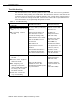
Set up stations B and C by assigning the first two BRI lines starting from the last DSL
that can be used to place and receive calls:
a. Assign
a line from the last DSL to station B:
(1).
Press
Menu
➜
SysProgram
➜
Exit
➜
Extensions
➜
LinesTrunks.
(2).
Enter the extension of the station.
(3).
Press
Enter.
(4).
Press the range corresponding to the logical ID for the BRI
line being assigned to the button or select
Entry Mode.
16 Basic Rate Interface (BRI) Provisioning Guide