
Instruction manual

MERLIN LEGEND Communications System Release 5.0
System Planning
555-650-112
Issue 1
June 1997
Control Unit Configuration
Page 2-15Numbering the System
2
NOTE:
If your list includes an 008 OPT module, draw a line after the twelfth
logical ID, but cross off the last four logical IDs, since these jacks
cannot be used to physically connect telephone equipment. The
extension numbers of these logical IDs can be used, however, for
applications requiring phantom extensions.
2. In the Jack Type column of Form 2a, do
one
of the following to indicate the
type of each extension jack next to its logical ID:
■ If the jack is analog, check A.
■ If the jack is digital, check D.
■ If the jack is basic telephone, check B.
You are now ready to match the system telephones and other equipment to these
available jacks. After calculating touch-tone receivers as described in the next
section, begin matching equipment and jacks with Jack for Primary Operator
Position, and proceed through the subsequent sections as appropriate for the
system.
Touch-Tone Receivers (TTRs) 2
Use these guidelines for calculating the system requirements for touch-tone
receivers for systems both with and without a voice messaging system (VMS).
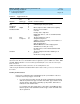
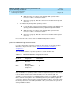
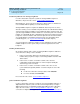
TTRs for the system are supplied by the modules listed in Table 2–2.
Table 2-2. Modules with Touch-Tone Receivers
NOTE:NOTE:NOTE:
A VMS
cannot
be directly connected to the 008 OPT module. However, the
TTRs supplied by the 008 OPT module can be used by the VMS.
A VMS requires a certain number of TTRs, in addition to any system requirements
for TTRs. The number of TTRs required by a VMS depends on the number of
ports used by the VMS (see Table 2-3
).
Module Number of TTRs
008 OPT 2
012 2
016 4
400 GS/LS/TTR 4
400 4
800 DID 2
800 GS/LS-ID 2